J&M 1325-20T User Manual
Page 24
22
Installation of Scale System
for Grain Carts Equipped with Tracks, Dual Wheels or Single Wheel
PARTS LIST (Weigh-Tronix)
(for Models 1000+ with
Single Wheels or Models 1250, 1251, 1325, 1326 and 1400
with Dual Wheels)
#
1
2
3
3
4
5
6
7
8
9
10
11
12
13
14
15
Part #
450WTS
278WB
640
915
JB-5
PC-2
-------
-------
MBI-2
WBW-278
BB-2
343BWN
MB-58612
MB-381
-------
MB-1434
Description
4 1/2” Weigh Spindle
2 7/8” Hitch Weigh Bar
640 Indicator
915 Indicator
5-Pt Junction Box (1325-D)
Power Cord to Battery
---------------
---------------
Mounting Bracket for Indicator
2 7/8” Weigh Bar Weldment
Battery Box with Strap
3/4” x 3” Bolt (Gr 8) with Heavy Lock
Washer and Nut
5/8” x 6 1/2” Bolt (Gr 5) with Nut
3/8” x 1” Bolt with Nut
----------------
1/4” x 3/4” Bolt with Nut
PARTS LIST (Digi-Star)
(for Track Carts, Models 1000+
with Single Wheels or Models 1050, 1051, 1130, 1131, 1150
and 1151 with Dual Wheels)
#
1
2
3
4
5
6
7
8
9
10
11
12
13
14
15
16
17
18
Part #
375WS
278WB-T
EZ-400L
JB-5
PC-1
ECI-1
37605SA
ATP-375-GS
MBI-1
WBW-278T
BB-2
343BWN
MB-58612
MB-381
PB-10
141837
Description
3 3/4” Dia. Weigh Spindle
2 7/8” Weigh Bar
Indicator Box
Junction Box (5 pt.)
Power Cord to Battery
Extension Cord (optional)
Seal (Hub)
4 1/2” OD Adapter Pipe Tubing
Mounting Bracket for Indicator
2 7/8” Weigh Bar Weldment
Battery Box with strap
3/4” x 3” Bolt (Gr 8) with Heavy Lock
Washer and Nut
5/8” x 6 1/2” Bolt (Gr 5) with Nut
3/8” x 1” Bolt with Nut
#10 Pan Bolt with Nut
30 ft. Standard Cable for J-Box to Indicator
1” x 5 1/2” Bolt (Gr5) with nut\
1” x 3” Bolt (Gr5) with nut and lockwasher
To connect the Power Cord to the Indicator Box, attach screw plug end of the Power Cord into the power port
of the Indicator Box. To connect to the battery, secure the Red Wire of the Power Cord to the Positive Terminal
of the battery and the Black Wire to the Negative Terminal. Be sure any additional wires provided by the Power
Cord are properly stored and secured.
CONNECTING THE POWER CORD
1.
Using the Junction Box as a template, mark and drill
holes on the inside face of the front left side leg of the
grain cart. The Junction Box should be positioned
approximately 23” above the top of the A-Frame.
After the holes have been drilled, secure the Junction
Box to the inside of the front left leg of the grain cart
using four 1/4” self tapping bolts.
Remove the cover from the Junction Box. Insert the
Hitch Weigh Bar wire through the center port and
connect to the center terminal of the Junction Box by
matching the colored wires. Repeat for the left and
right side weigh bar wires.
Connect the J-Box cable between the center terminal
and the indicator located on the front of the grain
cart leg.
Replace cover on Junction Box
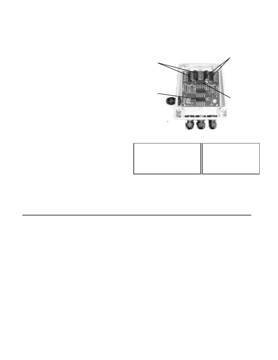
MOUNTING THE JUNCTION BOX
1.
2.
3.
4.
5.
Use Junction Box as a template to drill holes on
inside face of front grain cart leg.
Run Wires from
Right Weigh
Bars through
right port and
connect to right
side terminals.
Run Wires
from Left
Weigh Bars
through left
port and con-
nect to left side
terminals.
Run Wire from
Hitch Weigh Bar
through center
port and con-
nect to center
terminal.
Connect the
J-Box cable be-
tween the center
terminal and the
indicator located
on the front of the
grain cart leg.
Junction Box Wiring Diagram
+Exc = Green
-Exc = Black
+Sig = White
-Sig = Red
Shield = Orange or Orange-White
Junction Box Wiring Diagram
+Exc = Red
-Exc = Black
+Sig = White
-Sig = Green
Shield = Orange
Weigh-Tronix
Digi-Star