J&M 1325-20T User Manual
Page 23
21
Remove the 2 1/2” x 13 1/4” shaft from the swivel hitch by
unbolting the 1” x 5 1/2” Grade 5 bolt and locknut that at-
taches the swivel hitch and the 1” x 4 1/2” Grade 5 bolt and
locknut that attaches the rear collar.
Remove the eight 3/4” x 3” Grade 8 Bolts from the Hitch Spool
Plate Support located on the front of the A-Frame.
Bolt the Weigh Bar Weldment to the threaded holes located
on the rear of the A-Frame using four 3/4” x 3” Grade 8 bolts
with lockwashers.
Reuse the 1” x 5 1/2” Grade 5 bolt and locknut to secure the
Hitch Weigh Bar to the hitch.
Before installing the Hitch Weigh Bar, feed the wire through
the left side of the A-Frame tubing and exit the frame through
the hole located directly behind the front leg of the grain cart.
Slide the rear of the Hitch Weigh Bar through the Weigh Bar
Weldment and secure using the 1” x 4 1/2” Grade 5 bolt and
locknut. NOTE: Be sure the hitch weigh bar is secured in
the UP position as indicated by the decal on the weigh bar.
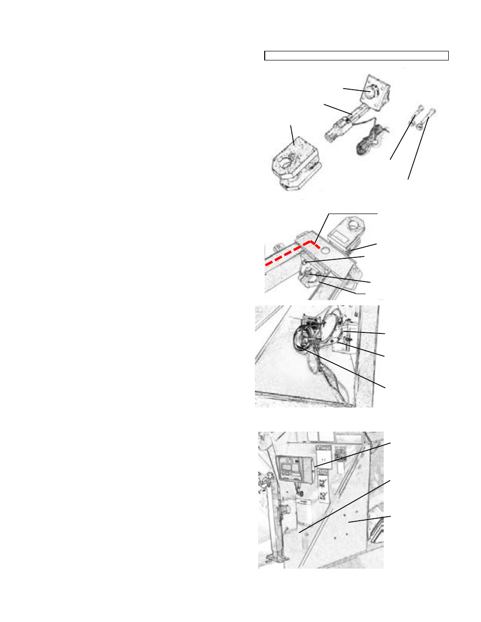
HITCH ASSEMBLY
1.
2.
3.
4.
5.
6.
Swivel Hitch
Weigh Bar
Weldment
1” x 4 1/2” Grade 5
Bolt with Lock Nut
Weigh Bar
1” x 5 1/2” Grade 5
Bolt with Lock Nut
HITCH PARTS
3/4” x 3” Gr 8 Bolt
Weigh Bar Weldment
Run Wire from
Weigh Bar through
Left Side of A-Frame
1” x 4 1/2” Gr 5 Bolt
1” x 5 1/2” Gr 5 Bolt
Installation of Scale System
for Grain Carts Equipped with Tracks, Dual Wheels or Single Wheel
A mounting bracket is included to mount the indicator to the
front leg of the grain cart. Using the mounting bracket as
a template, mark and drill 7/16” holes and 3/8 bolts or 1/4”
holes and bolts (GT400) on the front leg of the grain cart
approximately 33” above the top of the A-Frame.
Secure the mounting bracket to the front leg using two
3/8” x 1” flange bolts and nuts. Slide the Indicator across
the top of the mounting bracket and secure using two #10
bolts and nuts.
Connect the J-Box cable to the port on the bottom of the
Indicator.
(Note: An extension cord between the J-Box cable and the
Indicator is available to mount the Indicator in the tractor
cab if desired.)
MOUNTING THE INDICATOR
1.
2.
3.
MOUNTING THE BATTERY BOX
Using the Battery Box as a template, mark and drill
two 7/16” holes on the inside of the front leg approxi-
mately 16” above the A-Frame.
Secure the Battery Box to the leg of the grain cart
using two 3/8” x 1” flange bolt and nuts.
(12V Lawn and Garden Battery is not included)
1.
2.
Battery Box
mounted to inside
of front leg
Extension Cable
(to move Indicator
into tractor cab)
stored here.
Owner Supplied
Battery
Location of Bat-
tery Box (inside
of panel)
Location of Junc-
tion Box (inside
of panel)
Indicator with
Mounting
Bracket
(Inside View of Front Leg)