J&M 818 User Manual
Page 23
- 23 -
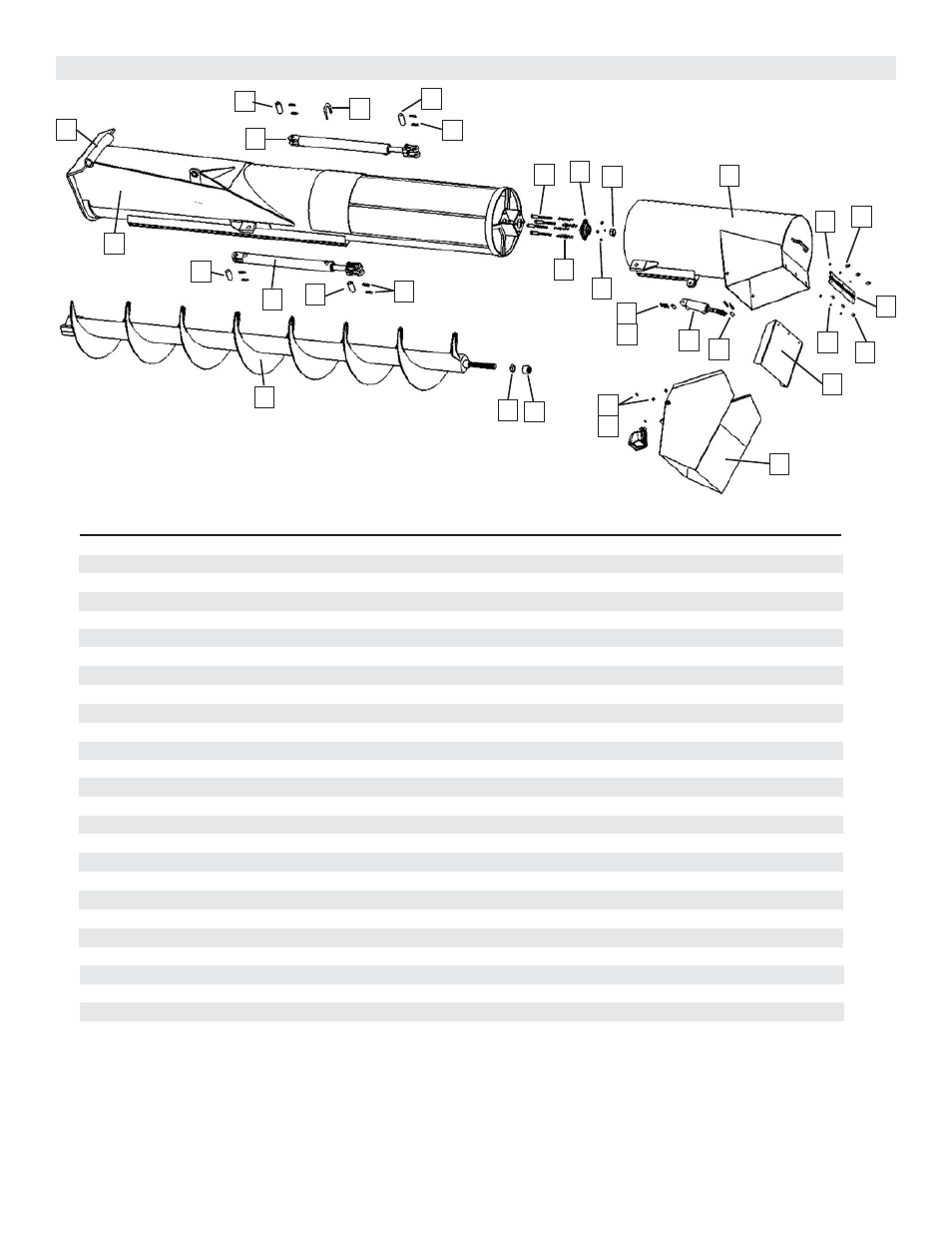
OPTIONAL HYDRAULIC SLIDING UPPER AUGER, TUBE AND FLOW CONTROL SPOUT ASSEMBLY
#
1
2
3
4
5
6
7
8
9
10
11
12
13
14
15
16
17
18
19
20
21
22
23
Part #
UAH-818BX
UF-18X
112S
HN-114
GRAF-206
MB-126
CMSUAA-4
12N
JD20024
ICR4
RP14
3825434U
-----
UAH-818BT
FSH-18E
HP-18
BP-18E
HC-FCS
CP-12112
88M6x20
88M6N
88M12x50
88M12N
Description
Upper Auger Housing, Lower (for optional hydraulic sliding auger)
18” Upper Flighting welded to 4 1/2” pipe (for optional hydraulic sliding auger)
1 1/2” Long Spacer
1 1/4” Hex Nut
1 1/4” Flange Bearing, 4 hole
1/2” x 5 1/2” Bolt
Compression Spring
1/2” Regular Nut
2” x 24” Hydraulic Cylinder
1” x 4” Pin
Roll Pin
2 1/2” Diameter x 4 3/4” Long U-Bolt with 3/8” Washer and Lock Nut
---------------
Upper Auger Housing, Upper (for optional hydraulic sliding auger)
18” Flow Control Spout Housing (for optional hydraulic sliding auger)
18” Hinge Plate
18” Baffl e Plate (for optional hydraulic sliding auger)
Hydraulic Cylinder with Clevis End
1/2” x 1 1/2” Clevis Pin
8.8M6 x 20 mm Bolt
8.8M6 Nut
8.8M12 x 50 mm Bolt
8.8M12 Nut
14
6
5
7
3
8
20
21
21
16
20
17
15
18
19
3
4
2
11
10
9
10
12
10
11
9
10
1
22
22
24
23
23