J&M 4WS17 User Manual
Page 11
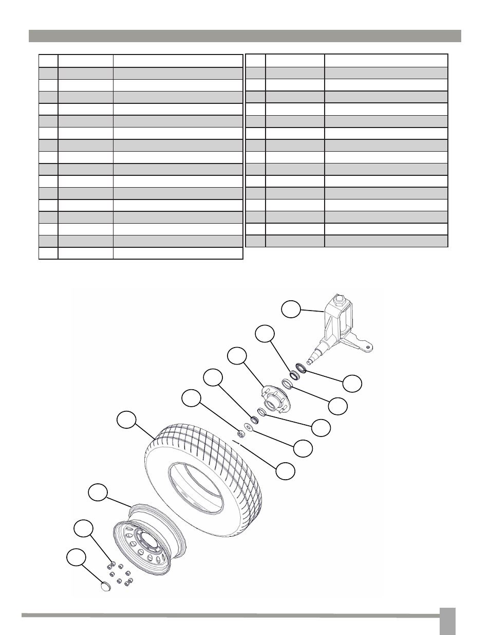
10
S
PIndle
& t
Ire
a
SSemblIeS
#
Part. No.
Description
1
JM0001606
1-1/4” Hex Nut
2
JM0009455
3/4” Bushing
3
JM0003181
3/4” Shoulder Bolt
4
JM0003184
3/4” Shoulder Bolt Nut
5
JM0003164
Rear Hitch Weldment
6
JM0003165
15 1/8” x 1-1/4” King Pin Weldment
7
JM0003166
Rear Axle Assembly
8
JM0003187
Left Spindle Weldment
9
JM0002408
5/8” Shoulder Bolt
10
JM0003185
5/8” Shoulder Bolt Nut
11
JM0003168
Ten Ton Clevis Weldment
12
JM0003180
15-1/2” x 1-3/4” King Pin Weldment
13
JM0003169
1-3/4” Bushing
14
JM0003189
Right Spindle Weldment
15
JM0002128
1-3/4” Hex Nut
16
JM0003188
Tie Rod
17
19
18
20
22
21
23
25
24
26
27
29
28
30
#
Part. No
Description
17
JM0003224
Grease Cap
18
JM0008525
9/16”-18 Lug nut
19
JM0003233
8 Bolt Wheel 16” Diameter
20
JM0003232
Tire 235-85-R16
21
JM0003065
1” x 3” Cotter Pin
22
JM0002139
1”-8 Castle Hex Nut
23
JM0003063
1” USS Flat Washer
24
JM0003218
Small Outer Bearing
25
JM0003222
Small Outer Race
26
JM0003231
7k Idler Hub
27
JM0003220
Inside Large Race
28
JM0003221
Inside Large Bearing
29
JM0003223
Inside Bearing Seal
30
JM0003187
Left Spindle Assembly
31
JM0003170
Right Spindle Assembly
*From the rear view, the front left and right spindle
assemblies are labeled correctly. The rear spindle
assemblies are reversed.