Set-up instructions – J&M TF215 User Manual
Page 12
Pg. 12
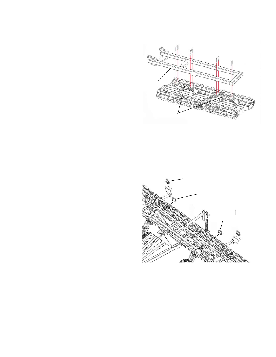
Front of
Wing
Frame
2 1/2” Torsion Arm
Red Light
Amber Light
Red Light
Amber Light
SET-UP INSTRUCTIONS
Step 7 – Installing the Wing Baskets
Secure the torsion-flex arm of the rolling basket
assembly to the rear tubing member of the Wing
Frame using two 5/8” x 4” x 5 1/2" U-Bolts and 5/8”
Lock Nuts.
Make sure the wing baskets are placed according to
the “Basket Sizes and Layout” section of the chart
found on page 5. IMPORTANT: Make sure the
wing baskets closest to the baskets on the Base
Unit baskets have a clearance of 2”. The spacing
between wing baskets should have a clearance
of 1 1/2”.
Note: Be sure the basket assemblies with the 2 1/2”
x 2 1/2” x 2’-0” torsion arms are secured to the side
wings. (The baskets on the base unit main frame should have a larger 3” x 3” torsion arm.)
Repeat for opposite side wing.
Step 8 – Installing the Wing Arm Rests
Attach the Wing Rest Arm to the Wing Frame as shown using four 1/2" x 1 1/2" Grade 5 Bolts and 1/2"
Lock Nuts. One wing rest arm is longer than the other. The longer wing arm should be mounted to the
left side wing and the short wing arm should be mounted to the right wing arm.
Step 9 – Mounting the Light Brackets and Lights
Mount the left and right Light Mounting Bracket to
the back of the Base Unit Main Frame using four
1/4” Self-Tapping Screws. Secure the Amber Light
to the mounting bracket using four 1/4” x 1” Grade 5
Bolts and 1/4” Lock Nuts. Place the Red Lights
approximately 18” from the hinges of the Main Base
Unit and secure to the top of the 4” x 4” tubing using
four self-tapping screws.
Snap the end plugs of each light into the light wiring
harness already located inside the frame of the Main
Frame Base Unit.