BVA Hydraulics P240L User Manual
Page 4
1. Read, understand, and follow the SET UP section on
page 4.
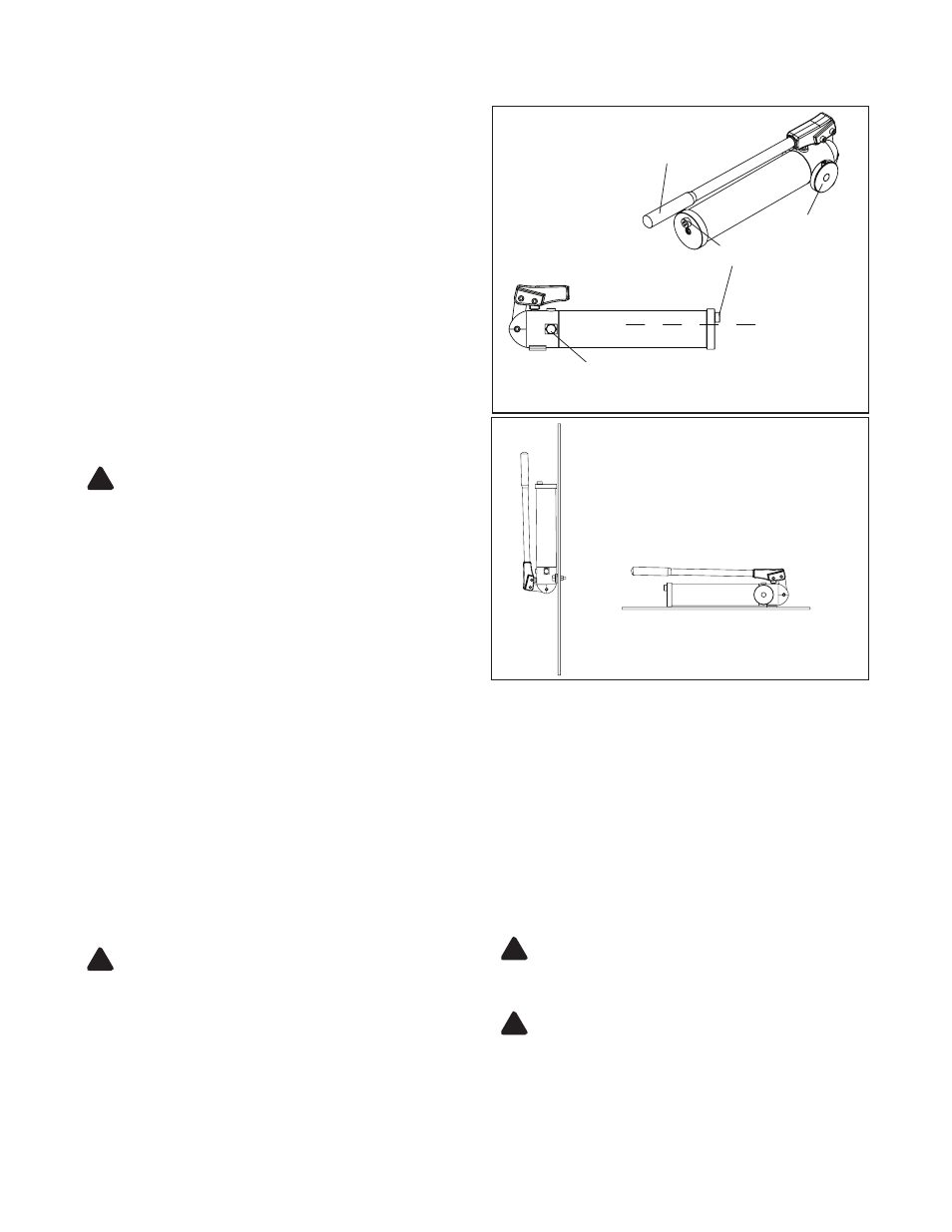
2. Pump may be used in any of the two positions shown in
Figure 6.
BEFOrE USE
1. Before using this product, read the instruction manual
completely and familiarize yourself thoroughly with the
product, its components and recognize the hazards
associated with its use.
2. Verify that the product and the application are compatible.
Inspect before each use. Do not use if bent, broken, leaking
or damaged components are noted.
3. Replace worn or damaged parts and assemblies with
BVA Hydraulics Authorized Replacement Parts only (See
Replacement Parts Section). Lubricate as instructed in
Maintenance Section.
4. Ensure method of confirming load is accurate and working
properly. Have gauge or load cell accuracy verified by
qualified personnel on a yearly basis.
5. Pump should be stored where protected from the
elements, abrasive dust, and temperature
extremes. Pump should be stored horizontally.
note: Pump may be used and stored vertically, but only
as oriented in Fig 4.
SEt UP
(refer to Figures 1, 3)
This pump’s maximum working pressure is
7,200 psi. Ensure that all hydraulic equipment
such as cylinders, hoses, couplers and etc. used with this
pump are rated at 7,200 psi or more.
1. Set the pump on a hard flat surface, i.e. a work bench.
Remove the oil filler screw found on rear end cap to check
fluid level. Correct fluid level is even with the oil filler screw
hole.
2. Carefully remove the threaded plug on oil outlet port. *Install
a pressure gauge in-line between the pump and application.
Port connection is 1/4”NPTF. It is recommended to use
a BVA CA3814 fitting, CF3814 gauge adapter, GW2514
gauge, and a CB1438 fitting to install.
These items must be purchased separately.
note:
Always secure threaded connections with non-hardening
pipe thread compound. Take care not to introduce compound
into port orifices. Tighten securely to prevent accidental
removal of components while in use.
3. Tighten securely to prevent accidental removal of
components while in use.
4. Check for leaks in system and repair by qualified personnel
as needed. Depressurize the hydraulic system before
servicing.
4
Figure 3
- Set Up Illustration
oil filler screw
release valve
operating handle
correct oil level
oil output port 1/4”-18NPTF
Figure 4
- Use / Storage Positions
* A load cell and digital display may be used in addition to
or
instead of a pressure gauge.
ALWAYS monitor pressure, load or position using
suitable equipment. Pressure may be monitored
by means of an optional manifold and gauge (contact BVA
Hydraulics). Load may be monitored by means of a load cell
and digital indicator. Correct application position can only be
determined by the operator of the equipment.
!
to Use:
A. Close release valve by turning it clockwise. Finger tighten
ONLY. Using tools on release valve can destroy the
pump.
B. Pump handle until desired pressure, load or position is
reached.
C. Secure load with appropriate means.
D. To retract application, turn the release valve knob slowly
counterclockwise (never more than 2 full turns).
NEVER operate pump with release valve closed and
disconnected from application.
OPEratIOn
!
NEVER rely on hydraulic pressure alone to secure
a load!
NEVER allow personnel to work or pass
under a load until the load is secured by cribbing, blocking,
or other mechanical means.
!
!