BVA Hydraulics PG6505 User Manual
Page 6
OPERATION
ALWAYS monitor pressure, load or position using suitable equipment. Pressure may be monitored by means of an optional
manifold and gauge (contact
BVA Hydraulics). Load may be monitored by means of a load cell and digital indicator. Correct
application position can only be determined by the operator of the equipment.
1. Check all system fittings and connections to be sure they are tight and leak free.
2. Check the engine oil level. Please refer to engine owner's manual.
3. Before starting the pump, always place the control valve lever in the middle (Neutral/Hold) position to prevent accidental lifting
or moving of load.
4. To start engine, refer to engine owner's manual.
5. Let the pump idle for a few minutes prior to operation.
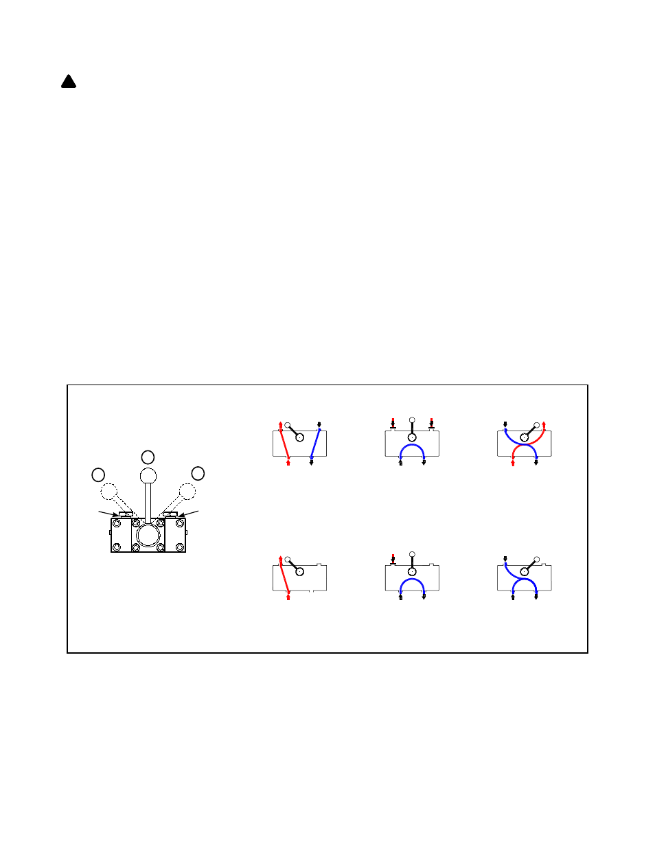
6. Use the control valve lever to control the direction of fluid flow. This gas engine pump is equipped with a 4-way 3-position valve.
Refer to figure 3(a) below for the flowpath.
Note: Do not continue to operate pump after cylinder plunger is fully extended or retracted.
7. To stop the engine, refer to engine owner's manual.
8. Depressurize all connections before disconnect.
Note: Control valve on this pump is 4-way, 3-position valve type, for use with double-acting cylinders. If your application requires
a 3-way setting for single-acting cylinder as shown in figure 3(b), it can be changed by an authorized BVA Service Center. If you
have any doubt, please contact BVA Technical Service 888-332-6419.
6
!
Position 1: Pressurized
oil flows to port A, port B
returns flow to reservoir
Position 3: Pressurized
oil flows to port B, port A
returns flow to reservoir.
Position 2: Neutral,
ports A and B are
closed. Hold Position.
Port A Port B
Port A Port B
Port A Port B
P R
P R
P R
(a) 4-way, 3-position valve for Double Acting Cylinder
Position 1 (Advance):
Pressurized oil flows to
port A.
Position 3 (Retract):
Port A returns flow to
reservoir
.
Position 2 (Hold):
Neutral, port A is closed.
Hold Position.
Port A
Port A
Port A
(b) 3-way, 3-position valve for Single Acting Cylinder
Port A
Port B
1
2
3
P R
P R
P R
Figure 3
- Flowpath of the valve positions and operations.