Fig1, Voltage ratio, "pull off"force between silver and ceramic layer – BeStar FT-39T-2.5B1 User Manual
Page 5: Signal, Fig.3 direction of lead wire (vertically), Fig.2 direction of lead wire (horizontally), Bestar electronics industry co.,ltd
T
h
is
p
ri
n
t
a
n
d
i
n
fo
rm
a
tio
n
t
he
re
i
n
a
re
p
ro
p
ri
e
ta
ry
t
o
B
e
s
ta
r
E
le
c
tr
o
n
ics
I
ndu
s
tr
y
C
o
.,
L
td.
a
nd
s
h
a
ll
no
t
b
e
u
s
ed
i
n
w
h
o
le
o
r
in
pa
rt
w
ith
ou
t
it
s
w
ri
tt
en
c
on
tent
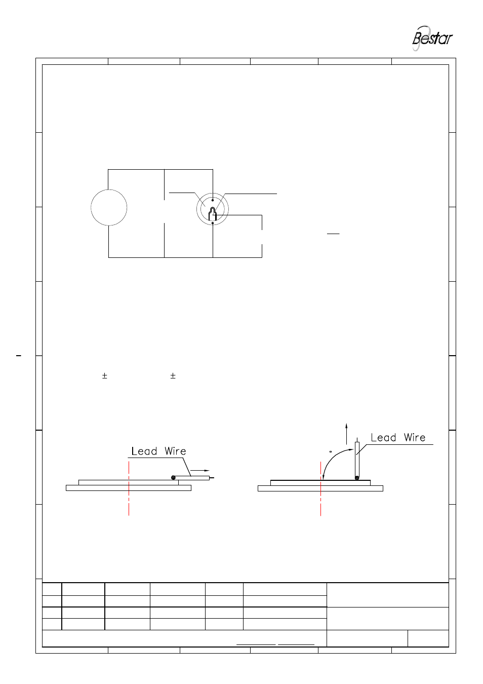
Note:
5.1 Lead wire (UL 1571 #24AWG)to be soldered on the silver by handsoldering
at 300 10
°C duration 2 0.5 sec
5.2.a Pull force by houizontal direction is ≥20N
5.2.b Pull force by vertical direction is ≥2.5N
李红元
Approved by:
Note
Date
Drawn
Rev.
BESTAR ELECTRONICS INDUSTRY CO.,LTD
6
5
4
Page:05 of 08
DRG NO: BS/TEY01.117J
3
2
1
09/08/31
汤浩君
赵
峥
FIG.3 Direction of Lead Wire
(vertically)
J 09/08/31 汤浩君
I 09/05/11 汤浩君
H 09/01/17 汤浩君
FIG.2 Direction of Lead Wire
(horizontally)
A
B
Date:
Checked by:
Drawn by:
C
D
FT-39T-2.5B1
Piezo Ceramic Element
A
B
90
C
D
4. Voltage ratio
The voltage ratio between electrode input and feedback electrode output at
resonant frequency is more than 2.5,see below
Feedback electrode
5."Pull off"force between silver and ceramic layer
S
E
F
FIG1
U
1
FT-39T-2.5B1
signal
G
H
electrode
U
0
≥
U
0
U
1
2.5
E
F
Voltage ratio:
G
H
6
5
4
博 士 達
3
2
1