Astro Pneumatic 1500CY 1-1/2 Ton Capacity Truck Transmission Jack User Manual
說明書需要訂裝成一本書 書的頁數順序請依照以下紅字標的頁數, Color, Product: 1500cys manual dimension
INFORMATIONS PRODUIT:
Product: 1500CYS Manual
Dimension:
A3 paper on both side
Date: 2010/12/17
Color:
Black
第5頁
PLEASE DO NOT RETURN ANY PRODUCT WITHOUT CALLING
1-800-221-9705 FOR INSTRUCTIONS
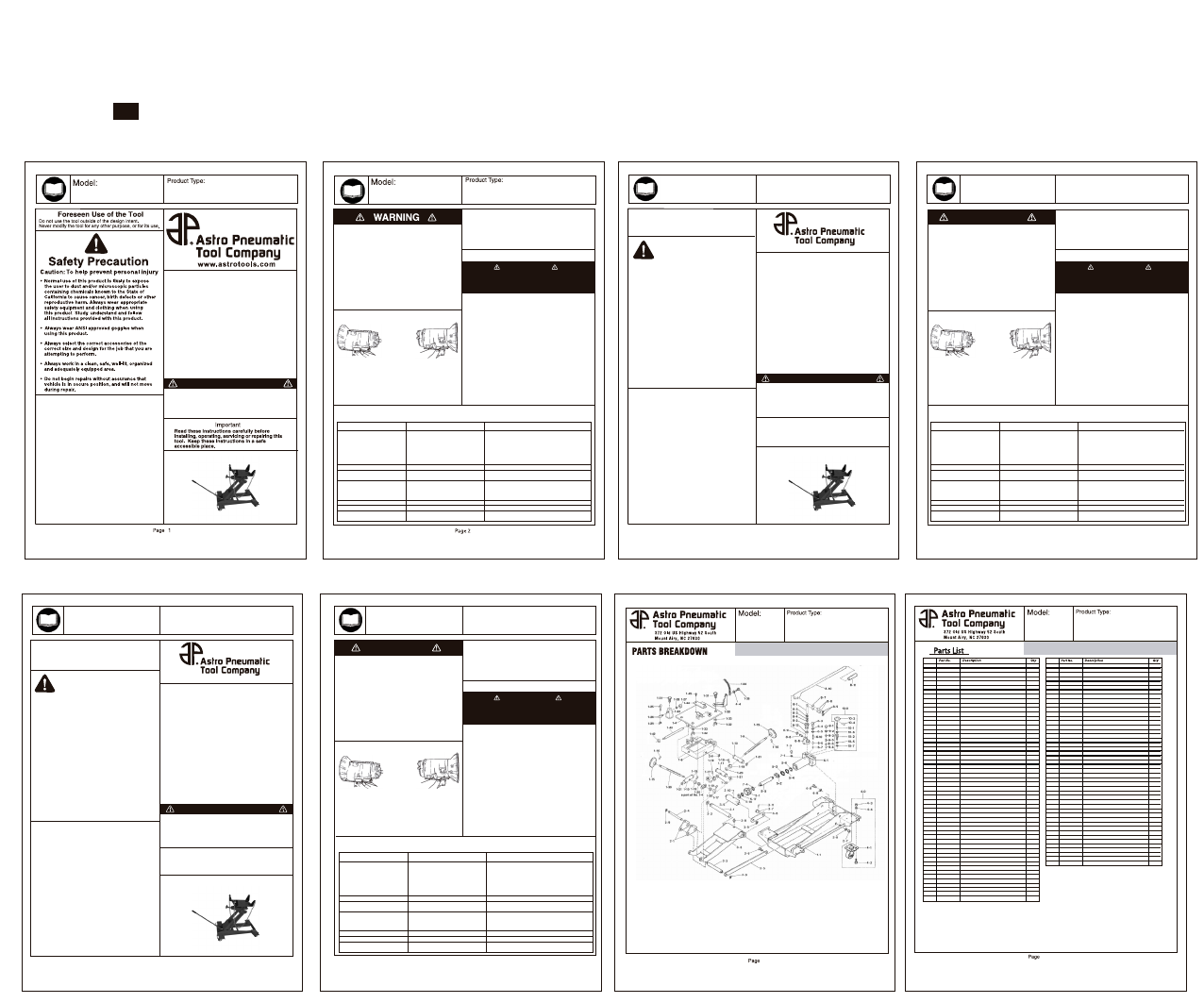
Unpacking
When unpacking, check the parts diagram and part number listing
on pages 3 to 4 to make sure all parts are included. If any parts are
missing or damage, please call your distributor.
MADE IN CHINA
第1頁
第6頁
第7頁
說明書需要訂裝成一本書
書的頁數順序請依照以下紅字標的頁數
第2頁
第3頁
第4頁
Call 1.800.221.9705 for questions concerning performance of the product
or other inquiries.
3
Página 1
INFORMACIÓN DEL PRODUCTO:
SPÉCIFICATIONS:
ESPECIFICACIONES:
S
ADVERTISSEMENT
ADVERTENCIA
• Designed for removal and installation of heavy-duty truck
transmissions or differentials
• Safety overload system prevents jack from
being used beyond its rated capacity
• Flash chrome ram prevents rust from entering the hydraulic system
• Fully adjustable universal saddle with adjustable corner brackets
and safety chain
• Pump handle rotates 360° for all position operation
• Safety by-pass system prevents damage to cylinder
• Four full-swivel ball bearing caster wheels for easy positioning
• Low frame easily clears undercarriage obstacles
• 4-way swivel
• MEETS ANSI STANDARD FOR PERFORMANCE AND SAFETY
Weight Capacity :
Min.Saddle Height :
Max.Saddle Height :
Hydraulic Lift :
Chassis Length :
Chassis Width :
Saddle Tilt Forward :
Saddle Tilt Backward :
Saddle Left & Right :
Net Weight :
1500CYS
1-1/2 TON CAPACITY TRUCK
TRANSMISSION JACK
1500CYS
1-1/2 TON CAPACITY TRUCK
TRANSMISSION JACK
1-1/2 TON CAPACITY TRUCK TRANSMISSION JACK
1-1/2 TON CAPACITY TRUCK TRANSMISSION JACK
1500CYS
1-1/2 TON CAPACITY TRUCK
TRANSMISSION JACK
1500CYS
1-1/2 TON CAPACITY TRUCK
TRANSMISSION JACK
OPERATING INSTRUCTIONS
1. Position the jack under the transmission.
2. Close the control valve. Operate the pump handle to raise
the boom and align the mounting plate with the transmission.
See Figure 1.
3. Remove the transmission according to the instructions
in the vehicle service manual.
4. Position the transmission on the mounting plate, resting
against the angle plates as shown in Figure 1.
1. Store the jack in a well-protected area where it will not be
exposed to corrosive vapors, abrasive dust, or any other
harmful elements.
2. Regularly lubricate the moving parts.
3. To check the oil level, place the jack on level ground and lower
the lift arm completely. Remove the filler plug. The oil level
should be within 3/8” of the filler plug hole. Do not overfill. If
necessary, add approved anti-wear hydraulic jack oil, and
install the filler plug again.
IMPORTANT: The use of alcohol, hydraulic brake fluid or
detergent motor oil could damage the seals
and result in jack failure.
4. Inspect the jack before each use. Take corrective action if
any of the following problems are found:
• Cracked or damaged housing
• Excessive wear, bending, or other damage
• Leaking hydraulic fluid
• Scored or damaged piston rod
• Malfunctioning swivel heads or adjusting screws
• Loose hardware
• Modified or altered equipment
5. Secure the transmission to the mounting plate.
• The mounting plate may be tilted forward
and backward by turning the tilt knob.
• The mounting plate may be tilted side-to-side by
adjusting the two vertical hex hd. cap screws.
6. Lower the load by slowly opening the control valve. The
control valve regulates how fast the boom is lowered.
MAINTENANCE
• Always read the manual and understand all operating and
safety instructions prior to operating and/or troubleshooting
this jack.
• Do not exceed the rated capacity of the jack. Operating at over
the rated capacity may cause serious injury and/or damage.
• Always place the jack on a solid, level surface while operating.
• Center the jack at a location under the vehicle recommended
by the manufacturer.
• Secure the vehicle from possible movement prior to lifting to
prevent serious injury and/or damage.
• The jack is a lifting device only. The load must be supported
with jack stands at locations under the vehicle recommended
by the manufacturer.
• When lowering the vehicle, turn the release valve slowly and
not more than two turns to prevent loss of load and cause
serious injury and/or damage.
Product Information
SPECIFICATIONS:
1500CYS
1-1/2 TON CAPACITY TRUCK
TRANSMISSION JACK
Página 2
Dirt is the greatest single cause of failure in hydraulic units. Keep the jack
clean and well lubricated to prevent foreign matter from entering the system.
If the jack has been exposed to rain, snow, sand, or grit, it must be cleaned
before it is used.
IMPORTANT
Dirt is the greatest single cause of failure in hydraulic units. Keep the jack
clean and well lubricated to prevent foreign matter from entering the system.
If the jack has been exposed to rain, snow, sand, or grit, it must be cleaned
before it is used.
IMPORTANT
Modèle:
Type de Produit:
1500CYS
1-1/2 TON CAPACITY TRUCK
TRANSMISSION JACK
Modèle:
Type de Produit:
Modelo:
Tipo de Producto:
1500CYS
1-1/2 TON CAPACITY TRUCK
TRANSMISSION JACK
Modelo:
Tipo de Producto:
Figure 1
Angle Plates
Angle Plates
The transmission
must rest against
the angle plates
as shown.
TROUBLESHOOTING
Jack does not lift
Jack lifts only partially
Jack advances slowly
Jack lifts load, but doesn’t hold
Jack leaks oil
Jack will not retract
Jack retracts slowly
1. Release valve is open.
2. Low/no oil in reservoir.
3. Air-locked system.
4. Load is above capacity of jack.
5. Delivery valve and/or bypass
valve not working correctly.
6. Packing worn out or defective
1. Too much or not enough oil
1. Pump not working correctly.
2. Leaking seals.
1. Cylinder packing is leaking.
2. Valve not working correctly (suction,
delivery, release, or bypass).
3. Air-locked system.
1. Worn or damaged seals
1. Release valve is closed.
1. Cylinder damages internally.
2. Link section is binding.
1. Close release valve.
2. Fill with oil and bleed system.
3. Bleed system.
4. Use correct equipment
5. Clean to remove dirt or foreign matter. Replace oil.
6. Replace power unit.
1. Check oil level.
1. Replace power unit.
2. Replace power unit.
1. Replace power unit.
2. Inspect valves. Clean and repair seat surfaces.
3. Bleed system.
1. Replace power unit.
1. Open or clean release valve.
1. Send jack to Astro authorized service center for repair.
2. Lubricate link section.
Trouble
Probable Cause
Remedy
1. Position the jack under the transmission.
2. Close the control valve. Operate the pump handle to raise
the boom and align the mounting plate with the transmission.
See Figure 1.
3. Remove the transmission according to the instructions
in the vehicle service manual.
4. Position the transmission on the mounting plate, resting
against the angle plates as shown in Figure 1.
1. Store the jack in a well-protected area where it will not be
exposed to corrosive vapors, abrasive dust, or any other
harmful elements.
2. Regularly lubricate the moving parts.
3. To check the oil level, place the jack on level ground and lower
the lift arm completely. Remove the filler plug. The oil level
should be within 3/8” of the filler plug hole. Do not overfill. If
necessary, add approved anti-wear hydraulic jack oil, and
install the filler plug again.
IMPORTANT: The use of alcohol, hydraulic brake fluid or
detergent motor oil could damage the seals
and result in jack failure.
4. Inspect the jack before each use. Take corrective action if
any of the following problems are found:
• Cracked or damaged housing
• Excessive wear, bending, or other damage
• Leaking hydraulic fluid
• Scored or damaged piston rod
• Malfunctioning swivel heads or adjusting screws
• Loose hardware
• Modified or altered equipment
5. Secure the transmission to the mounting plate.
• The mounting plate may be tilted forward
and backward by turning the tilt knob.
• The mounting plate may be tilted side-to-side by
adjusting the two vertical hex hd. cap screws.
6. Lower the load by slowly opening the control valve. The
control valve regulates how fast the boom is lowered.
ENTRETIEN
• Always read the manual and understand all operating and
safety instructions prior to operating and/or troubleshooting
this jack.
• Do not exceed the rated capacity of the jack. Operating at over
the rated capacity may cause serious injury and/or damage.
• Always place the jack on a solid, level surface while operating.
• Center the jack at a location under the vehicle recommended
by the manufacturer.
• Secure the vehicle from possible movement prior to lifting to
prevent serious injury and/or damage.
• The jack is a lifting device only. The load must be supported
with jack stands at locations under the vehicle recommended
by the manufacturer.
• When lowering the vehicle, turn the release valve slowly and
not more than two turns to prevent loss of load and cause
serious injury and/or damage.
Figure 1
Angle Plates
Angle Plates
The transmission
must rest against
the angle plates
as shown.
RÉSOLUTIONS DES PROBLÈMES
Jack does not lift
Jack lifts only partially
Jack advances slowly
Jack lifts load, but doesn’t hold
Jack leaks oil
Jack will not retract
Jack retracts slowly
1. Release valve is open.
2. Low/no oil in reservoir.
3. Air-locked system.
4. Load is above capacity of jack.
5. Delivery valve and/or bypass
valve not working correctly.
6. Packing worn out or defective
1. Too much or not enough oil
1. Pump not working correctly.
2. Leaking seals.
1. Cylinder packing is leaking.
2. Valve not working correctly (suction,
delivery, release, or bypass).
3. Air-locked system.
1. Worn or damaged seals
1. Release valve is closed.
1. Cylinder damages internally.
2. Link section is binding.
1. Close release valve.
2. Fill with oil and bleed system.
3. Bleed system.
4. Use correct equipment
5. Clean to remove dirt or foreign matter. Replace oil.
6. Replace power unit.
1. Check oil level.
1. Replace power unit.
2. Replace power unit.
1. Replace power unit.
2. Inspect valves. Clean and repair seat surfaces.
3. Bleed system.
1. Replace power unit.
1. Open or clean release valve.
1. Send jack to Astro authorized service center for repair.
2. Lubricate link section.
Problèmes
Causes
Résolutions
1. Position the jack under the transmission.
2. Close the control valve. Operate the pump handle to raise
the boom and align the mounting plate with the transmission.
See Figure 1.
3. Remove the transmission according to the instructions
in the vehicle service manual.
4. Position the transmission on the mounting plate, resting
against the angle plates as shown in Figure 1.
1. Store the jack in a well-protected area where it will not be
exposed to corrosive vapors, abrasive dust, or any other
harmful elements.
2. Regularly lubricate the moving parts.
3. To check the oil level, place the jack on level ground and lower
the lift arm completely. Remove the filler plug. The oil level
should be within 3/8” of the filler plug hole. Do not overfill. If
necessary, add approved anti-wear hydraulic jack oil, and
install the filler plug again.
IMPORTANTE: The use of alcohol, hydraulic brake fluid or
detergent motor oil could damage the seals
and result in jack failure.
4. Inspect the jack before each use. Take corrective action if
any of the following problems are found:
• Cracked or damaged housing
• Excessive wear, bending, or other damage
• Leaking hydraulic fluid
• Scored or damaged piston rod
• Malfunctioning swivel heads or adjusting screws
• Loose hardware
• Modified or altered equipment
5. Secure the transmission to the mounting plate.
• The mounting plate may be tilted forward
and backward by turning the tilt knob.
• The mounting plate may be tilted side-to-side by
adjusting the two vertical hex hd. cap screws.
6. Lower the load by slowly opening the control valve. The
control valve regulates how fast the boom is lowered.
MANTENIMIENTO
• Always read the manual and understand all operating and
safety instructions prior to operating and/or troubleshooting
this jack.
• Do not exceed the rated capacity of the jack. Operating at over
the rated capacity may cause serious injury and/or damage.
• Always place the jack on a solid, level surface while operating.
• Center the jack at a location under the vehicle recommended
by the manufacturer.
• Secure the vehicle from possible movement prior to lifting to
prevent serious injury and/or damage.
• The jack is a lifting device only. The load must be supported
with jack stands at locations under the vehicle recommended
by the manufacturer.
• When lowering the vehicle, turn the release valve slowly and
not more than two turns to prevent loss of load and cause
serious injury and/or damage.
Dirt is the greatest single cause of failure in hydraulic units. Keep the jack
clean and well lubricated to prevent foreign matter from entering the system.
If the jack has been exposed to rain, snow, sand, or grit, it must be cleaned
before it is used.
IMPORTANTE
Figure 1
Angle Plates
Angle Plates
The transmission
must rest against
the angle plates
as shown.
LOCALIZACIONES DE AVERÍAS
Jack does not lift
Jack lifts only partially
Jack advances slowly
Jack lifts load, but doesn’t hold
Jack leaks oil
Jack will not retract
Jack retracts slowly
1. Release valve is open.
2. Low/no oil in reservoir.
3. Air-locked system.
4. Load is above capacity of jack.
5. Delivery valve and/or bypass
valve not working correctly.
6. Packing worn out or defective
1. Too much or not enough oil
1. Pump not working correctly.
2. Leaking seals.
1. Cylinder packing is leaking.
2. Valve not working correctly (suction,
delivery, release, or bypass).
3. Air-locked system.
1. Worn or damaged seals
1. Release valve is closed.
1. Cylinder damages internally.
2. Link section is binding.
1. Close release valve.
2. Fill with oil and bleed system.
3. Bleed system.
4. Use correct equipment
5. Clean to remove dirt or foreign matter. Replace oil.
6. Replace power unit.
1. Check oil level.
1. Replace power unit.
2. Replace power unit.
1. Replace power unit.
2. Inspect valves. Clean and repair seat surfaces.
3. Bleed system.
1. Replace power unit.
1. Open or clean release valve.
1. Send jack to Astro authorized service center for repair.
2. Lubricate link section.
Problema
Causa
Solución
www.astrotools.com
Lire ces instructions attentivement avant d’installer,
d’utiliser, d’entretenir et de réparer cet outil. Conserver
ces instructions dans un endroit sécuritaire et accessible.
IMPORTANT
Lors du déballage, vérifier que les pièces contenues dans
le schéma et la liste des numéros de pièces des pages 3 à 4
sont toutes incluses. Si une pièce est manquante ou abîmée,
veuillez appeler immédiatement votre distributeur.
Déballage
VEUILLEZ NE PAS RETOURNER DE PRODUIT AVANT D'AVOIR
APPELE 1-800-221-9705 POUR OBTENIR DES INSTRUCTIONS
FABRIQUÉ EN CHINE
Page 2
Page 1
Utiliser uniquement cet outil pour l’usage pour lequel il a
été conçu. Ne jamais modifier l’outil pour un but autre
que sa fonction d’origine prévue.
Utilisation Prévue
• L’utilisation normale de ce produit pourrait exposer
l’utilisateur à de la poussière et/ou des particules
microscopiques contenant des produits chimiques que
l’État de la Californie a reconnu comme étant une cause de
cancer, de déficience congénitale et d’autres effets nocifs
sur le système reproductif. Toujours porter un équipement
et des vêtements sécuritaires appropriés en utilisant ce
produit. Étudier, comprendre et suivre toutes les
instructions fournies avec ce produit.
• Toujours porter des lunettes à coques approuvées par
l’ANSI lorsque vous utilisez ce produit.
• Toujours utiliser les accessoires adéquats
pour le travail que vous effectuez.
• Toujours travailler dans un environnement propre,
sécuritaire, bien éclairé, organisé et suffisamment équipé.
• NE JAMAIS commencer les réparations sans d’abord
vous être assuré que le véhicule est en position sécurisée
et ne bougera pas lors de la réparation.
Mise en garde: Pour aider à prévenir les blessures
Mesure de Sécurité
www.astrotools.com
Cuando desempaque el producto, revise el diagrama y la lista
de piezas en páginas 3 y 4 para verificar que se hayan enviado
todas las piezas. De perder piezas o tener piezas dañadas,
favor llamar a su distribuidor inmediatamente.
Desempacado
Lea las instrucciones detenidamente antes de instalar,
operar, dar servicio o reparar esta herramienta. Guarde
estas instrucciones en un lugar seguro y accesible.
IMPORTANTE
POR FAVOR NO DEVOLVER CUALQUIER PRODUCTO SIN
LLAMAR 1-800-221-9705 PARA OBTENER INSTRUCCIONES
HECHO A CHINA
Uso Previsto de la Herramienta
Use esta herramienta exclusivamente para el fin que fue
diseñada. Nunca modifique la herramienta por cualquier otro
motivo que no sea la función programada.
• El uso normal de esta herramienta puede exponer al
usuario al polvo o a partículas microscópicas que
contienen sustancias químicas que se conocen en el
estado de California por causar cáncer, defectos del
nacimiento u otros daños reproductivos. Siempre use
equipo y ropa de seguridad adecuados para trabajar con
esta herramienta. Lea, comprenda y siga todas las
instrucciones incluidas con esta herramienta.
• Siempre use guantes del tipo aprobado por la ANSI para
trabajar con esta herramienta.
• Siempre usar los correctos accesorios para el trabajo
que Ud. está realizando.
• Trabaje siempre en un área limpia, segura, bien iluminada,
organizada y equipada adecuadamente.
• NUNCA empiece reparaciones sin estar seguro de que el
vehículo esté en posición segura y que no se mueva
durante la reparación.
Precaución: Para ayudar a evitar lesiones a las personas
Advertencias de Seguridad
1-1/2 TON CAPACITY TRUCK TRANSMISSION JACK
DIRECTIVES DE FONCTIONNEMENT
INSTRUCCIONES DE OPERACIÓN
• Designed for removal and installation of heavy-duty truck
transmissions or differentials
• Safety overload system prevents jack from
being used beyond its rated capacity
• Flash chrome ram prevents rust from entering the hydraulic system
• Fully adjustable universal saddle with adjustable corner brackets
and safety chain
• Pump handle rotates 360° for all position operation
• Safety by-pass system prevents damage to cylinder
• Four full-swivel ball bearing caster wheels for easy positioning
• Low frame easily clears undercarriage obstacles
• 4-way swivel
• MEETS ANSI STANDARD FOR PERFORMANCE AND SAFETY
Weight Capacity:
Min. Saddle Height:
Max. Saddle Height:
Hydraulic Lift:
Chassis Length:
Chassis Width:
Saddle Tilt Forward:
Saddle Tilt Backward:
Saddle Left & Right:
Net Weight:
3,000lbs. (1-1/2 Ton)
9" (225mm)
35-3/4" (905mm)
26-3/4" (690mm)
44-1/2" (1130mm)
25-1/2" (650mm)
30°
15°
12°
312lbs. (142kg)
1
1
1
1
1
1
2
2
2
2
7
4
4
2
2
2
2
2
2
2
4
4
4
2
2
1
1
2
1
2
2
2
1
1
2
2
2
2
4
1
1
1
1
2
2
1
2
1
2
4
4
16
16
16
Frame
Plate
Tilting Saddle
Screw
Pin with Female Screw
Pin
Grip
Spring Pin
Collar
Collar
Set Screw
Thrust Bearing
Snap Ring
Bracket (LH)
Hook with Thread
Pin for Hook
Nut
Spring Washer
Wing Nut
Bracket (RH)
Bolt
Wing Nut
Washer
Chain
Bolt
Screw
Shaft for Tilting
U Type Nut
Cover
Bolt
Spring Washer
Arm Connecting Joint
Link Rod Pin
Arm Pin
Link Rod
Link Rod Pin
Nut
Spring Washer
Snap Ring
Arm Pin
E-type Ring
Arm
Connecting Joint
Tension Rod
Tension Rod Pin
1500CYS-1-1
1500CYS-1-4
1500CYS-1-6
1500CYS-1-9
1500CYS-1-10
1500CYS-1-11
1500CYS-1-15
1500CYS-1-16
1500CYS-1-17
1500CYS-1-18
1500CYS-1-19
1500CYS-1-20
1500CYS-1-21
1500CYS-1-24
1500CYS-1-25
1500CYS-1-26
1500CYS-1-27
1500CYS-1-28
1500CYS-1-29
1500CYS-1-30
1500CYS-1-31
1500CYS-1-32
1500CYS-1-33
1500CYS-1-34
1500CYS-1-35
1500CYS-1-39
1500CYS-1-40
1500CYS-1-42
1500CYS-1-44
1500CYS-1-45
1500CYS-1-46
1500CYS-2-1
1500CYS-2-3
1500CYS-2-4
1500CYS-2-5
1500CYS-2-6
1500CYS-2-7
1500CYS-2-8
1500CYS-2-9
1500CYS-3-1
1500CYS-3-2
1500CYS-3-3
1500CYS-3-5
1500CYS-3-6
1500CYS-3-7
1500CYS-3-8
1500CYS-3-9
1500CYS-3-10
1500CYS-3-11
1500CYS-4-0
Grease Nipple
Snap Ring
Cotter Pin
Cotter Pin
Castor Assembly
Caster
Bolt
Nut
Spring Washer
1500CYS-4-1
1500CYS-4-2
1500CYS-4-3
1500CYS-4-4
Call 1.800.221.9705 for questions concerning performance of the product
or other inquiries.
1500CYS
1/2 TON CAPACITY TELESCOPING
TRANSMISSION JACK
第11頁
4
5-1
5-2
5-3*
5-4
5-5
5-14
5-17
6-1
6-3
6-4
6-5*
6-6*
6-7*
6-8
6-9
6-10
7-2
7-3
7-4
8-1
8-2
8-3*
8-4*
8-5*
8-6
8-7
8-8
8-9*
8-10
8-11
8-12*
9-1
9-2
9-3
9-4
9-5
9-6
10-0
10-1
10-2
10-3
10-4
10-5*
10-6*
10-7*
10-8
1500CYS-5-1
1500CYS-5-2
1500CYS-5-3*
1500CYS-5-4
1500CYS-5-5
1500CYS-5-14
1500CYS-5-17
1500CYS-6-1
1500CYS-6-3
1500CYS-6-4
1500CYS-6-5*
1500CYS-6-6*
1500CYS-6-7*
1500CYS-6-8
1500CYS-6-9
1500CYS-6-10
1500CYS-7-2
1500CYS-7-3
1500CYS-7-4
1500CYS-8-1
1500CYS-8-2
1500CYS-8-3*
1500CYS-8-4*
1500CYS-8-5*
1500CYS-8-6
1500CYS-8-7
1500CYS-8-8
1500CYS-8-9*
1500CYS-8-10
1500CYS-8-11
1500CYS-8-12*
1500CYS-9-1
1500CYS-9-2
1500CYS-9-3
1500CYS-9-4
1500CYS-9-5
1500CYS-9-6
1500CYS-10-0
1500CYS-10-1
1500CYS-10-2
1500CYS-10-3
1500CYS-10-4
1500CYS-10-5*
1500CYS-10-6*
1500CYS-10-7*
1500CYS-10-8
Tank Nut
Packing Seat
UN seal ring
Washer
Snap Ring
Oil Seal
O-Ring
Cylinder Assembly
Cap Plug
Back-Up Ring
O-Ring
Steel Ball
Steei Ball
Bolt
Spring Washer
Spring
O-Ring
Cap
O-Ring
Pump Plunger
Plunger Guide
Back-Up Ring
O-Ring
Oil Seal
Lever Branket
Link
Pin
Snap Ring
Lever
Knob
Copper Packing
Cap Plug
O-Ring
Nut
Steel Ball
Spring
Spring Seat
Release Valve Assembly
Release Valve
Release Valve Guide
Release Valve Grip
Spring Pin
O-Ring
O-Ring
Packing
Repair Kit
1
1
1
1
1
1
1
1
1
1
1
1
1
2
2
1
1
1
1
1
1
1
1
1
1
2
3
6
1
1
1
1
1
1
1
1
1
1
1
1
1
1
1
1
1
1
Index
No.
Items marked with an (*) are available in the Repair Kit
1-1
1-4
1-6
1-9
1-10
1-11
1-15
1-16
1-17
1-18
1-19
1-20
1-21
1-24
1-25
1-26
1-27
1-28
1-29
1-30
1-31
1-32
1-33
1-34
1-35
1-39
1-40
1-42
1-44
1-45
1-46
2-1
2-3
2-4
2-5
2-6
2-7
2-8
2-9
3-1
3-2
3-3
3-5
3-6
3-7
3-8
3-9
3-10
3-11
4-0
4-1
4-2
4-3
4-4
Index
• Astro Pneumatic Tool Co. warrants our products to the original user against
defective material or workmanship for a period of 1 year from the date of 1st use.
Astro reserves the right to determine whether the product failed because of
defective material, workmanship or other causes and to charge back for missing
parts. Astro Pneumatic Tool Co., at its discretion, will repair products covered
under this warranty free of charge. The original user is to return the product (with
the exceptions listed below) with the distributor’s name, address, adequate proof of
date of purchase or a copy of warranty card, and a short note explaining the
problem.
Failures caused by accident, alteration, or misuse are not covered
by this warranty.
• Astro will replace free of charge defective power unit on select hydraulic
equipment during warranty period. After warranty period repair parts are
available, please call (800)221-9705 for specific information.
• Astro Pneumatic Tool Co. or its authorized service representatives must perform all
warranty repairs. Any repair to the product by unauthorized service representatives
voids this warranty. The rights under this warranty are limited to the original user
and may not be transferred to subsequent owners.
• This warranty is in lieu of all other warranties, expressed or implied, including
warranties of merchantability and fitness for a particular purpose. Some states do
not allow the exclusion of limitations of incidental or consequential damages so the
above limitations may not apply to you.
1 YEAR LIMITED WARRANTY
• Astro Pneumatic Tool Co., Garantiza su producto solo al usuario original contra
materiales o mano de obra defectuosos por 1 año a partir de la fecha del 1ra de
uso. Astro se reserva el derecho a determinar si el producto falló a causa de
material defectivo, mano de obra u otras causas y de vuelta a cargo de las piezas
que faltan. Astro Pneumatic Tool Co. a su discreción, sera reparar los productos
cubiertos bajo esta garantía de forma gratuita. El distribuidor debe dirigir el usuario
original para devolver el producto (con las excepciones que se enumeran a
continuación) con el nombre del distribuidor, dirección, una prueba de la fecha de
compra o una copia de la tarjeta de garantía, y una breve nota explicando el
problema.
Fallas causadas por accidentes, alteración ,o uso indebido no están
cubiertos por esta garantía.
• Astro remplazara libre de cargos, las unidades de poder defectuosas de
equipo hydraulico seleccionado durante el periodo de garantia. Despues del
periodo de garantia puede obtener las partes para reparacion llamando
al telefono # (800) 221-9705 y para obtener mas informacion.
• Astro Pneumatic Tool Co. o de sus representantes de servicio autorizado debe
realizar todas las reparaciones bajo garantía. Cualquier reparación que el producto
no autorizado por los representantes de servicio los huecos de esta garantía. Los
derechos bajo esta garantía están limitados al usuario original y no podrán
transferirse a los propietarios posteriores.
• Esta garantía es en lugar de cualquier otra garantía, expresa o implícita, incluidas
las garantías de comerciabilidad y adecuación para un propósito en particular.
Algunos estados no permiten la exclusión de las limitaciones de daños incidentales
o consecuentes por lo que las limitaciones no pueden aplicarse a usted.
GARANTÍA LIMITADA DE UN AÑO
• Astro Pneumatic Tool Co. garantit nos produits à son utilisateur d'origine contre tout
matériau déficient ou défaut de fabrication pour une période d'1 an à partir de la
date de la 1ére utilisation. Astro se réserve le droit de déterminer si le produit est
déficient à cause du matériau ou d'un défaut de fabrication ou d'autres causes et de
faire payer pour toute pièce manquante. Astro Pneumatic Tool Co., réparera
gratuitement, à sa discrétion, les produits couverts par cette garantie. Le distribu-
teur devrait rediriger l'utilisateur d'origine pour le renvoi de produit (avec les
exceptions énumérées ci-dessous) avec le nom du distributeur, son adresse et les
preuves adéquates de la date d'achat ou une copie de la carte de garantie et un
court message expliquant le problème.
Les défaillances provoquées par
accident, altération ou mauvais usage ne sont pas couvertes par cette
garantie.
• Astro va remplacer gratuitement l’unité de puissance défectueuse sur
l’équipement hydraulique sélectionné pendant la période de garantie. Après la
période de garantie, les pièces de réparation sont disponibles,veuillez appeler
(800) 221-9705 pour les informations spécifiques.
• Astro Pneumatic Tool Co. ou ses représentants officiels du SAV doivent exécuter les
réparations sous garantie. Toute réparation d'un produit par un SAV non autorisé
annule cette garantie. Les droits liés à la garantie se limitent à l'utilisateur d'origine
et ne peuvent être transférés à tout autre utilisateur suivant.
• Cette garantie remplace toutes les autres garanties explicites ou implicites et toutes
les garanties implicites de commercia bilité et d'adaptation à un usage particulier.
Certaines provinces n’autorisent pas l’exclusion ou la imitation des dommages
circonstanciels ou fortuits, de sorte que l’exclusion ou la limitation ci-dessus peuvent
donc ne pas vous concerner.
GARANTIE LIMITÉE D'1 AN
3,000lbs. (1-1/2 Ton)
9" (225mm)
35-3/4" (905mm)
26-3/4" (690mm)
44-1/2" (1130mm)
25-1/2" (650mm)
30°
15°
12°
312lbs. (142kg)