Warning, Unit labeling – Anemostat RF11 User Manual
Page 4
1220 Watson Center Road • Carson, CA 90745
Tel: (310) 835-7500 • Fax: (310) 835-0448
www.anemostat.com • [email protected]
4
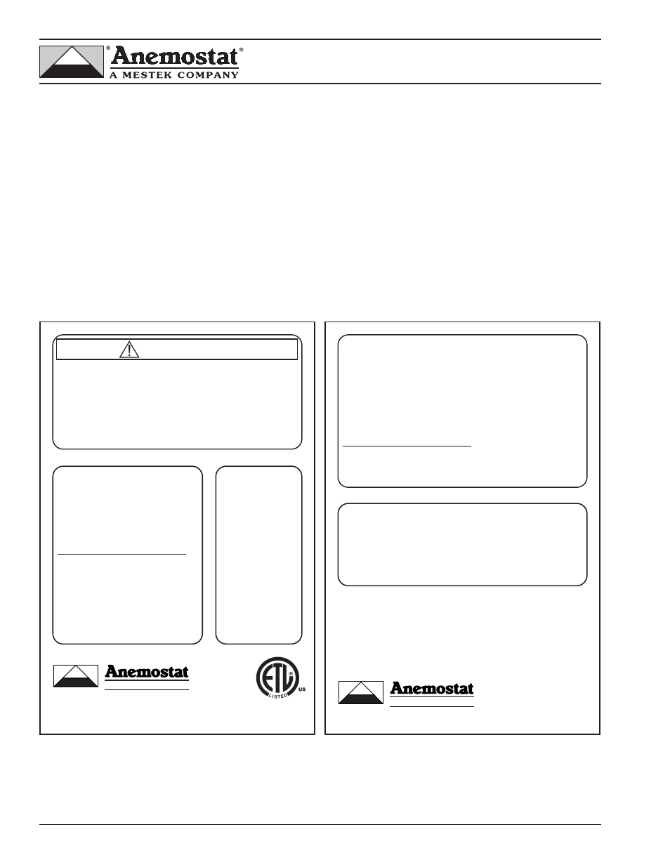
Unit Labeling
Labels are applied to each terminal as follows:
• Unit specific nameplate showing model number, manufactured date, and information regarding controls and heat
provided as appropriate.
• The appropriate airflow calibration chart indicating the airflow at varying airflow sensor signals as shown on pages
8, 9, and 10.
• The appropriate wiring/piping diagram for controls provided by Anemostat. Refer to controls manual CM-1 for
controls adjustment and troubleshooting procedures.
• Up arrow indicating the proper orientation of the unit for installation.
• Airflow direction arrow indicating the proper orientation of the duct connections.
• Sheet Metal Workers Union logo indicating unit produced by members of The Sheet Metal Workers Union.
Nameplate for terminals with electronic analog controls or
DDC controls
Nameplate for terminals with pneumatic controls without
electric heat.
Made in the USA
WARNING
HAZARDOUS VOLTAGE!
RISK OF ELECTRIC SHOCK
CAN CAUSE INJURY OR DEATH
DISCONNECT ALL REMOTE POWER
SUPPLIES BEFORE SERVICING
Model: RF-11
Size: XX
Order: XXXXXX
Mfg. Date: XX/XX/XX
Control Package: XXXXX
Location: XXXXXXXXXXXXX
Heater Data: See heater name plate
Heater Min. Airflow Req’d: XXX CFM
DESIGN AIRFLOW RATES / SIGNAL
Min CFM:
XXX
/
XX VDC
Max CFM: XXX
/
XX VDC
Aux CFM: XXX
/
XX VDC
Use copper power supply wiring only
®
A MESTEK COMPANY
®
CARSON, CA 310-835-7500
L-27C1
3031533
Conforms to
UL STD 1996
UL STD 429
SINGLE DUCT AIR TERMINAL WITH ELECTRIC HEAT
TA
G
:
XX
XX
XX
Made in the USA
AIR TERMINALS
Model: RF-11
Size: XX
Order: XXXXXX
Mfg. Date: XX/XX/XX
Control Package: XXXXX
Location: XXXXXXXXXXXXX
DESIGN AIRFLOW RATES / SIGNAL
Min CFM:
XXX
/
XX VDC
Max CFM: XXX
/
XX VDC
Aux CFM: XXX
/
XX VDC
®
A MESTEK COMPANY
®
CARSON, CA 310-835-7500
L-54C1
TAG:
XXXXXX