Aeromotive 13224 - A1000, 4-PORT CARBURETED BYPASS REGULATOR User Manual
Page 2
The following steps are typical of most installations:
1. Once the engine has been allowed to cool, disconnect the negative battery cable and relieve any fuel
system pressure.
2. Place shop towels around the existing regulator to catch any gasoline that is spilled during this step of
the installation. Remove any regulator mounting hardware and connecting fuel lines, then carefully
remove the existing regulator.
3. Find a suitable place in the vehicle’s engine compartment to mount the Aeromotive regulator. Using
the supplied mounting bracket as a template, mark the bracket mounting holes and drill to accept a
#10 screw.
4. With the bracket attached to the regulator, mount the bracket and regulator to the vehicle using two
#10 screws, nuts and lock washers.
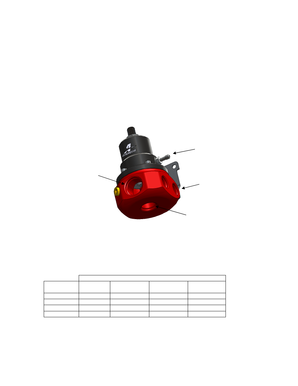
5. Attach the fuel supply line to the AN-10 inlet port located in the front of the regulator using a cutoff AN-
10 style fitting (Aeromotive P/N 15608 or equivalent) and o-ring.
6. Measure the length of the required bypass line, using the chart below determine the minimum
required return line ID based this length. Attach the fuel return line to the AN-08 bypass port located at
the bottom of the regulator using the appropriately sized fitting, Aeromotive p/n 15605 for a AN-06 line,
p/n 15607 for a AN-08 line, p/n 15641 for a AN-10 line.
Minimum Return Fuel Line ID Chart
Fuel Pump Free Flow Rating (GPH)
Return Line
Length (ft.)
1 to 60
GPH
60 to 120
GPH
120 to 180
GPH
180 to 250
GPH
0-5 feet
3/8”
3/8” 1/2” 1/2”
5-10 feet
3/8”
1/2” 1/2” 5/8”
10-15 feet
3/8”
1/2” 5/8” 3/4”
15-20 feet
1/2” 1/2”
5/8
3/4”
Note: An undersized return line will prevent the fuel pressure regulator from functioning properly.
AN-10 Inlet Port
Vac/Boost
Ref Port
By-pass Port
AN-06 Outlet Ports