Elmo Rietschle V-VC 50/75/100/150 User Manual
Page 20
20
|
www.gd-elmorietschle.com © Gardner Denver Schopfheim GmbH, Gardner Denver Deutschland GmbH
Maintenance and repair
s
2
U
D
s
1
G
f
2
f
4
f
4
h
1
f
3
g
1
h
7.2.1 Air fi ltering
NOTICE
Insuffi cient maintenance on the air fi lter
The power of the machine lessens and damage may
occur to the machine.
Intake air fi lter:
The micro fi lter (Fig. 4/f
2
) must be cleaned by rinsing
out or purging or replaced more or less often de-
pending on how dirty the discharged medium is.
Remove the cover (Fig. 4/G) after undoing the
screws ( Fig. 4/s
1
) and remove the suction fl ange
(Fig. 4/D) after undoing the screws (Fig. 4/s
2
).
Re-assemble in reverse order. After that check the
function of the valve. For this purpose fi t a shut-off
device (enclosed volume min. 1 litre) on the suction
side and starts vacuum pump shortly. Afterwards
the vacuum achieved must remain constantly.
Gas ballast valve fi lter:
The pumps work with a gas ballast valve (Fig. 4/U).
The inbuilt fi lter disc Fig. 5/f
3
) and micro fi lter discs
Fig. 5/f
4
) must be cleaned more or less often by
purging depending on how dirty the medium fl ow-
ing through is. By undoing the countersunk screw
(Fig. 5/g
1
) and removing the plastic cover (Fig. 5/h
1
)
the fi lter parts can be removed for cleaning.
Re-assemble in reverse order.
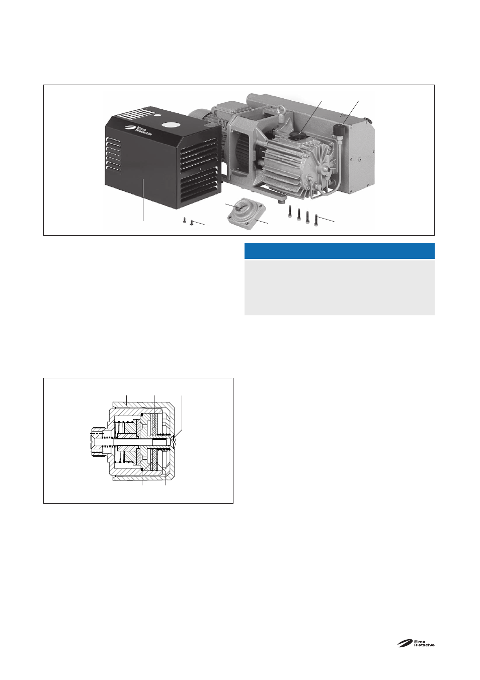
Fig.. 4 Air fi ltering
D
Suction fl ange
G Cover
U
Gas ballast valve
f
2
Micro
fi lter
h Valve
s
1
Lens fl ange screw
s
2
Screws
Fig. 5 Gas ballast valve
h
1
Cover
f
3
Filter
disc
g
1
Countersunk
screw
f
4
Micro
fi lter discs