Elmo Rietschle C-VLR 250/300/400/500 User Manual
Page 25
25
www.gd-elmorietschle.com © Gardner Denver Schopfheim GmbH, Gardner Denver Deutschland GmbH
|
Maintenance and repair
s
4
q
k
m
n
2
m
s
5
q
n
1
v
k
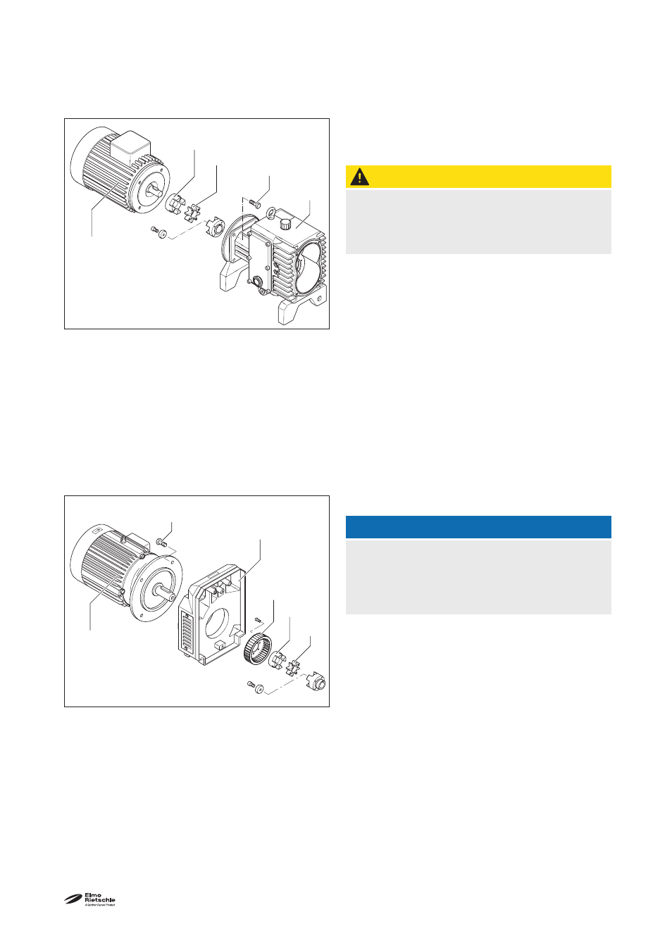
7.2.3 Coupling
The coupling sprocket (Fig. 10/k, 11/k)) is subject to
wear and must be checked regularly (at least once a
year).
CAUTION
Defective coupling sprocket
Defective sprockets may lead to the rotor shaft
breaking.
To check the coupling switch the motor
(Fig. 10/m, 11/m) off and ensure that it cannot be
switched on again.
C-VLR 60
Undo the screws (Fig. 10/s
4
) on the housing fl ange
(Fig. 10/n
1
) . Remove the motor axially with the
half of the coupling on the motor side (Fig. 10/q)
and suspend with the lifting device. If the sprocket
(Fig. 10/k) is damaged or worn, then replace it.
C-VLR 100 - 500
Undo the screws (Fig. 11/s
5
) on the motor fl ange.
Remove the motor with the coupling half on the
motor side (Fig. 11/q) from the fanhousing (Fig. 11/
n
2
) axially and suspend using a lifting tool. If the
sprocket (Fig. 11/k) is damaged or worn, then re-
place it. The fan (Fig. 11/v) should also be checked
for damage from time to time and replaced if neces-
sary.
NOTICE
Frequent starting up and high ambient tem-
perature
The service life of the sprocket (Fig. 10/k, 11/k) is
reduced.
Re-assemble in reverse order.
Fig. 10 Coupling C-VLR 60
k
Coupling sprocket
m
Motor
n
1
Housing
q
Coupling half on the motor side
s
4
Screws
Fig. 11 Coupling C-VLR 100- 500
k
Coupling sprocket
m
Motor
n
2
Fan housing
q
Coupling half on the motor side
s
5
Screws
v Fan