Figure d - pvc pipe installation figure c – Liberty Pumps ALM-2R User Manual
Page 3
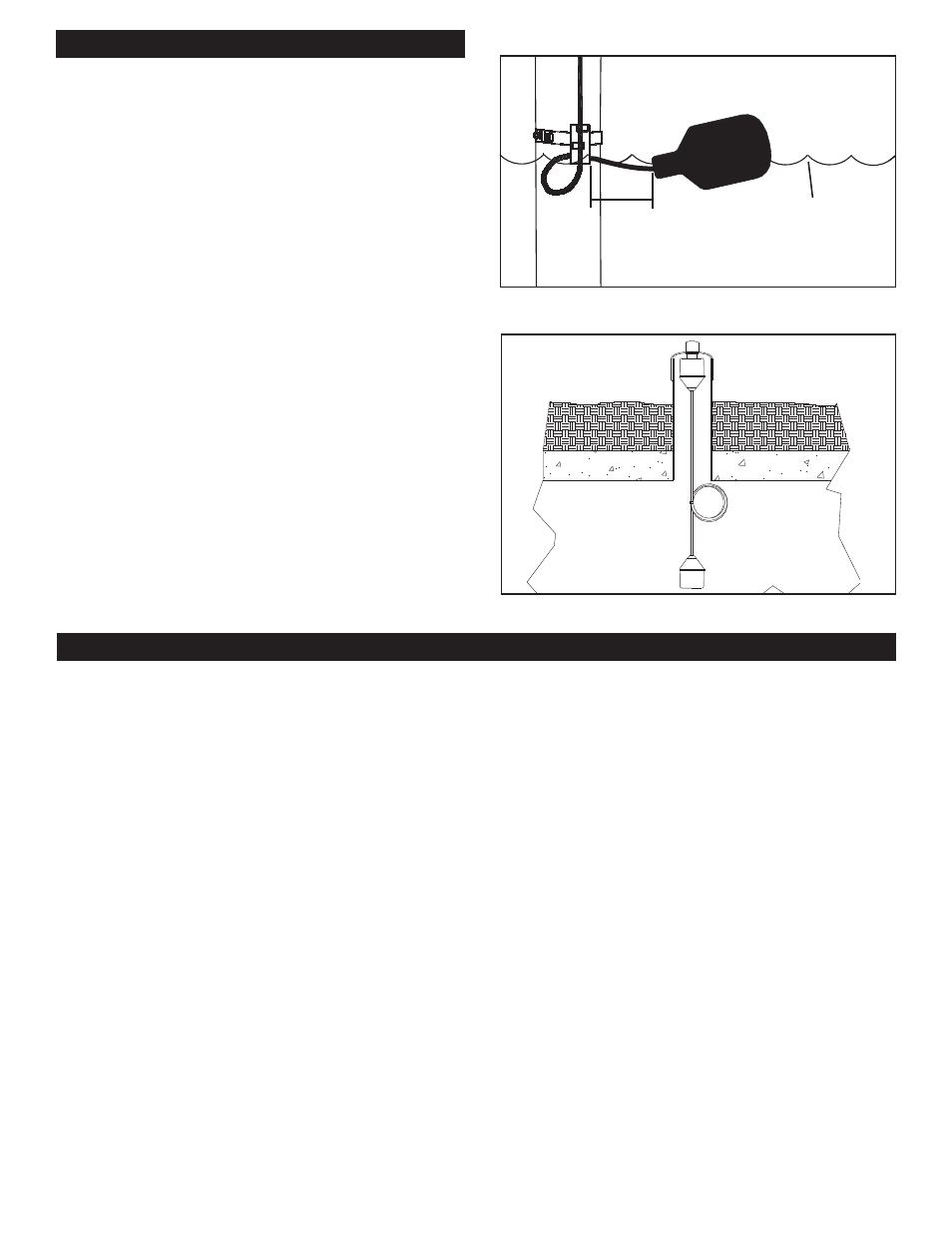
INSTALLING THE TRANSMITTER (FLOAT)
NOTE: DO NOT CUT FLOAT CABLE.
1. To monitor high level conditions determine the correct
activation level for the fl oat.
2. Suspend switch at desired activation level as shown
in Figure C. Note: Switch remains partially submerged
during "on" tipping action.
3. Set
fl oat height and coil any excess cord. Secure with
zip tie provided.
4. To mount the unit in a 4 or 6 inch PVC pipe, drill a 1 3/8
inch hole in the top of the PVC cap and mount transmitter
through the cap as shown in Figure D.
5. Reinstall battery and place back inside unit.
6. Apply thread compound that is suitable for PVC to threads
of holder. Do not use tefl on tape.
7. Replace grey cap. Wait at least three minutes. Once
battery is installed, the transmitter will wait three minutes
to transmit a signal. During the 3 minute wait, drop the
fl oat into place and replace all tank covers.
8. After three minutes have elapsed, press and hold "test"
and "silence" buttons on receiver. A fl ashing green light
signifi es a good installation. A fl ashing red light signifi es
either the unit did not receive any signal or the signal was
not strong enough for reliable operation. Move receiver to
a different location. Note: A change in location as minor
as moving it up vertical one foot could allow it to operate
reliably.
9. Replace battery every 2 years.
ALARM LIGHT KEY
Solid Red: Remote Alarm
Remote (wireless) alarm has been triggered. Check location of transmitter unit to determine if an alarm condition is occurring.
Fast Blink Red: Local Alarm
Local alarm (fl oat connected to terminal block) has been triggered. Check chamber in which local alarm fl oat is used.
Slow Blink Red: No Signal
The receiver is not communicating with the transmitter. Check transmitter battery voltage (3.6V) and/or the area between transmitter
and receiver for obstructions such as large vehicles or RV.
Slow-Fast Blink Red: Multiple Alarms
Several alarms are triggered.
1. Check local alarm fl oat (if used).
2. Check level in the tank with a remote alarm.
3. Check transmitter battery.
Solid Green: Primary Power
120 VAC power present.
Green Light Off:
Unit is no longer operating off of 120 VAC power and is operating off of 9 VDC battery backup (if battery is installed).
Horn Chirp:
Low battery or non-alkaline battery was used.
Replace 9 VDC backup battery with a new alkaline battery.
Figure D - PVC Pipe Installation
Figure C
approximate activa-
tion level
of 1.5 inches
above or below
horizontal
3.5 inch
tether
length