Installation instructions – Liberty Pumps D3696-Series User Manual
Page 3
©Copyright 2011 Liberty Pumps Inc. All rights reserved 3
D3600
Series
System
Pre-installation checklist:
1. Inspect the unit upon arrival to ensure that there is
no shipping damage. Pay careful attention to the
condition of the fiberglass basin, control floats,
pump guide rail brackets, and control panel. Notify
the carrier immediately if there is any damage.
2. Read all instructions and familiarize yourself with
the unit’s operation prior to proceeding with the
installation.
3. A qualified licensed electrician should install and
test all electrical circuits.
4. Check to ensure that your power source is adequate
to handle the pump amperage as noted above and on
the pump nameplate. Ensure that the electrical supply
circuit is equipped with fuses or breakers of the proper
capacity.
5. A separate 115V branch circuit should be installed for
the control circuit. We do not recommend splitting
the incoming pump power circuit to power the control
circuit.
6. All electrical connections should be tested to ensure
that a proper ground has been established
3
Installation Instructions
1.
Excavation:
Excavate the hole for the basin as small as possible, with a minimum base diameter of 50
”. Never
place the basin in direct contact with rocks or other sharp objects. Place enough fine, 1/8" to 3/4" pea gravel or
1/8" to 1/2" washed, crushed stone at the bottom of the excavation to create a minimum of 12 inches stone or
gravel after compaction. Do not use sand or native soil as backfill*. Properly compact underneath the basin to
provide a solid, level base that can support the weight of the filled basin. If a concrete pad will be used under the
basin, the compacted stone sub-base can be reduced to 6 inches.
2.
Connections & Backfill:
Pour enough concrete over and around the anti-floatation flange to anchor the basin
and prevent upward movement. Connect 2
” schedule 80 PVC pipe to the pump discharge. Do not reduce the
size of the discharge piping, and do not increase the discharge piping to larger than 3
”. The remainder of the
discharge line should be as short as possible with a minimum number of turns. Connect the inlet line
to the 4”
inlet hub with a rubber donut (Liberty #6112000). Connect the electrical coupling to 2
” electrical conduit and run
the power and float cords through the conduit to the control panel. The remaining backfill should be only fine, 1/8"
to 3/4" pea gravel or 1/8" to 1/2" washed, crushed stone. Do not use sand or native soil as backfill*. Do Not exert
heavy pressure or run heavy equipment over the backfill material, as it may cause tank collapse.
*Other backfill options may be available
– consult the factory for special instructions relative to your situation.
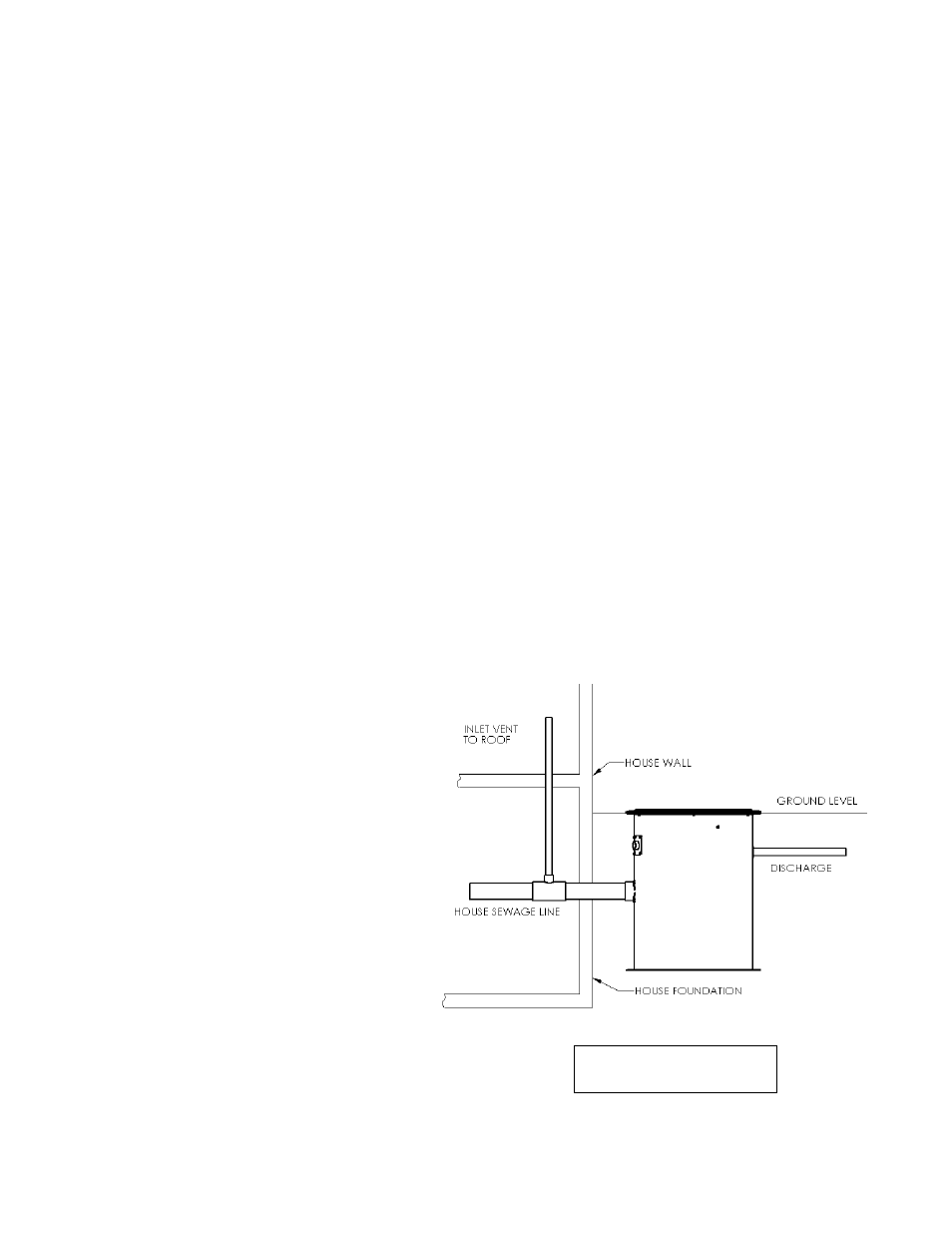
3.
Venting:
The fiberglass basin provided
with the system must be completely sealed
and properly vented in order to meet health
and plumbing code requirements. The
system is designed to be vented through
the inlet to an existing building vent stack.
In order to accomplish this, there must be
no traps between the system inlet and the
nearest building vent stack connection.
See Figure A for an example. If this is not
possible or desirable in your application, a
vent flange or grommet can be installed in
a hole cut into the solid fiberglass cover.
Figure A
– Inlet Venting