Effluent applications – Liberty Pumps 290-Series User Manual
Page 5
©Copyright 2012 Liberty Pumps Inc. All rights reserved
5
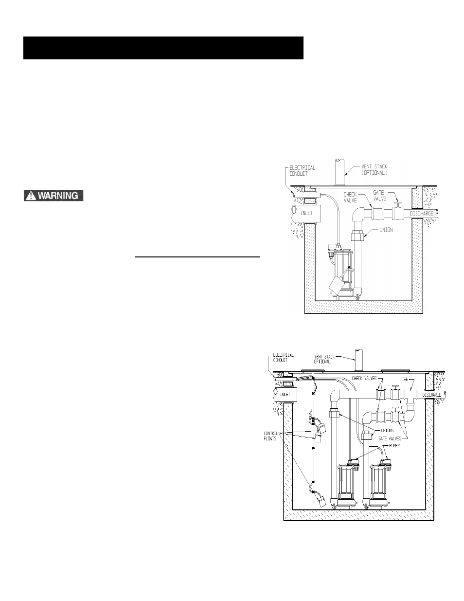
Fig. 2 – Typical Installation Simplex System
This is a recommended installation only.
Variations may apply.
Fig. 3 – Typical Installation Duplex System
This is a recommended installation only.
Variations may apply.
Vertical Magnetic Float (VMF) models (257, 287 and 297) are not recommended for effluent applications due to their short
On/Off cycle. Wide angle float models are better suited for effluent applications and are easily adjustable for different
On/Off levels.
The basin required for effluent applications must be sealed and vented to meet health and plumbing code requirements.
Proper basin size and basin materials for effluent applications vary depending on the type of effluent system and local
codes. Check with your local codes official prior to purchasing and installing the basin. Follow the manufacturer's
recommended guidelines for installation of your specific basin. A minimum diameter of 18" and depth of 24" is required
for proper pump operation, but larger basins are preferred for longer pump cycles and increased switch life. Installation
should be at a sufficient depth to ensure that all plumbing is below the frost line. If this is not feasible, delete the check
valve and size the basin and/or adjust the pump differential to
accommodate the additional backflow.
These pumps are not to be installed in locations
classified as hazardous in accordance with the National
Electric Code, ANSI/NFPA 70, or where prohibited by
local codes.
A.
Simplex (One Pump) Systems (see Fig. 2): Set the pump in place
making sure the float has adequate clearance to the side wall of the
basin. The float must be
free to move throughout its travel and
not contacting the pump body, piping, or other objects. If an optional
control device or float is used, follow the directions for mounting that
accompany the optional control. Connect the discharge pipe to the
pump's threaded discharge. IMPORTANT: DO NOT REDUCE THE
DISCHARGE PIPE SIZE BELOW THAT WHICH IS PROVIDED ON
THE PUMP. Contact Liberty Pumps or other qualified person if you
have questions regarding proper pipe sizes and flow rates. Mount
the basin cover making sure it is properly sealed.
Installation of Discharge: After the pump has been mounted,
install the discharge line. A union should be installed to
facilitate pump removal if necessary. A free-flow swing check
valve is recommended after the union to prevent the backflow
of liquid after each pumping cycle. A gate valve should follow
the check valve to allow periodic cleaning of the check valve or
removal of the pump. The remainder of the discharge line
should be as short as possible with a minimum number of
turns, to minimize friction head loss. Contact Liberty Pumps or
other qualified person if you have questions regarding proper
pipe sizes and flow rates.
(All Liberty effluent/dewatering pumps come equipped with an
air bleed hole in the base of the pump to help prevent airlock.
A small spray of water from this hole is normal while pump is
running.)
B.
Duplex (Two Pump) Systems (see Fig. 3): Set both pumps
in place in the bottom of the basin. The duplex control used
will include 3 or 4 floats that will either be tethered to one of
the discharge pipes or to an independent rod or bracket.
3. Effluent Applications