Dewatering / sump applications – Liberty Pumps 290-Series User Manual
Page 4
©Copyright 2012 Liberty Pumps Inc. All rights reserved
4
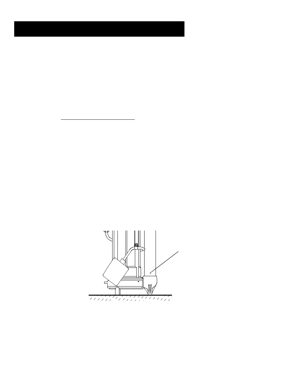
Fig. 1 – Anti-airlock hole position
1. For ordinary ground water pumping applications, a sump pit of not less than 14" in diameter is recommended.
Vertical float (VMF) models (257, 287 and 297) may be used in a minimum 10" diameter sump; however, a larger
diameter pit is preferred as it allows for a longer pump cycle and reduced switch cycling. The minimum depth of the
pit should be 18".
2. If the pit is not already enclosed on the bottom, provide a hard level bottom of bricks or concrete. DO NOT place
the pump directly on earth, gravel or debris since this can cause excessive wear of the impeller and possible
jamming.
“The Brick” (sold by Liberty Pumps as part # 4445000) is a pre-molded stable platform designed to fit
your submersible pump. It raises the pump 2.5” off the bottom of the pit, reducing the potential for jamming from
rocks and debris. Contact your local distributor to order. Remove all debris from the bottom of the sump pit
before installation of the pump. A sump pit cover is suggested for safety and to prevent foreign objects from
entering the pit.
3. Set the pump in the pit making sure the switch has adequate clearance and will not hang-up on the pit wall. The
float must be
free to move throughout its travel and not contacting the pump body, piping, or other objects. A 1-
1/2" threaded discharge is provided for connection of the discharge pipe. Do not reduce the discharge size to
below 1-1/2”. Schedule 40 PVC pipe is recommended; however, flexible discharge hose kits may be used for
temporary installations.
4. Connect the pipe or the discharge hose to the discharge of the pump. HAND TIGHTEN ONLY. Over tightening
may cause the pump housing to crack. Install a union or other means of separating the discharge line just above
the floor to facilitate removal of the pump if necessary. A check valve is recommended just above or in place of
the union to prevent the backflow of water after each pump cycle. (All Liberty effluent/dewatering pumps come
equipped with an air bleed hole in the base of the pump to help prevent airlock. A small spray of water from this
hole is normal while pump is running.)
5. Connect additional piping as needed to direct the discharge to the desired location. Discharge should be kept as
short as possible with a minimum number of turns. Check all connections for security.
6. Install a union or other means of separating the discharge pipe just above the floor to facilitate removal of the
pump if necessary.
A check valve is recommended just above, or in place of, the union to prevent the
backflow of water after each pump cycle.
7. If a check valve is used,
a 1/8” anti-airlock hole should be drilled in the discharge pipe just above the
pump’s discharge outlet to prevent pump “airlock” (see Fig. 1)
8. For added protection, consider the addition of a back-up pump such as
Liberty’s SJ10 SumpJet, as well as an
alarm such as
Liberty’s ALM-2 in applications where loss of pump function could result in property damage. If
an alarm is used, it must be connected to a separate electrical circuit.
2. Dewatering / Sump Applications
Drill 1/8” anti-
airlock hole.
Water spray is
normal.