Installation – Liberty Pumps HT40-Series User Manual
Page 3
©Copyright 2012 Liberty Pumps Inc. All rights reserved 3
2. Installation
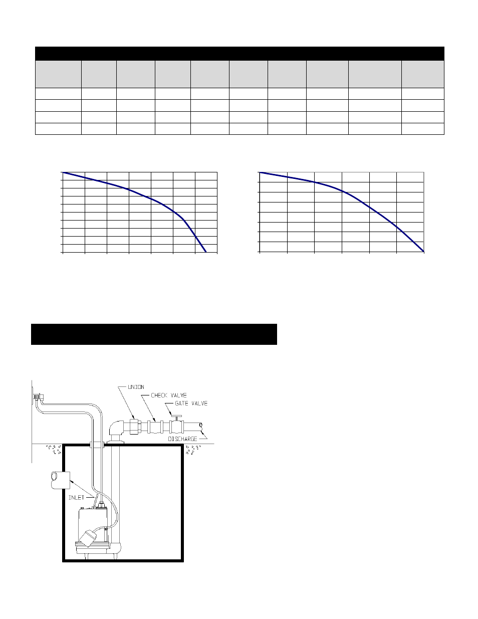
Fig. 1 – Typical Installation
This is a recommended installation only. Variations may apply.
MODEL SPECIFICATIONS
Model
HP
Volts
Phase
Full
Load
Amps
Cord
Length
Solids
Handling
FNPT
Discharg
e
Automatic
or Manual
Shut-off
Head
HT41M
4/10
115
1
12
10 ft.
¾”
1½”
Manual
20’
HT41M-2
4/10
115
1
12
20 ft.
¾”
1½”
Manual
20’
HT41A
4/10
115
1
12
10 ft.
¾”
1½”
Automatic
20’
HT41A-2
4/10
115
1
12
20 ft.
¾”
1½”
Automatic
20’
Set the pump in place making sure the float has adequate clearance
to the side wall of the basin. If an optional control device or float is
used, follow the directions for mounting that accompany the optional
control. Connect the discharge pipe to the pump's threaded
discharge.
IMPORTANT: DO NOT REDUCE THE DISCHARGE
PIPE SIZE BELOW THAT WHICH IS PROVIDED ON THE PUMP. In
some applications, it may be necessary to increase the pipe size to
reduce friction losses. Contact Liberty Pumps or other qualified
person if you have questions regarding proper pipe sizes and flow
rates.
After the pump has been mounted, install the remaining discharge
line. A union should be installed just above the cover to facilitate
pump removal if necessary. A check valve is recommended after the
union to prevent the backflow of liquid after each pumping cycle. A
gate valve should follow the check valve to allow periodic cleaning of
the check valve or removal of the pump.
The remainder of the discharge line should be as short as possible
with a minimum number of turns, to minimize friction head loss. Do
not restrict the discharge below that which is provided on the pump.
Larger pipe sizes may be required to eliminate friction head loss over
long runs. Contact Liberty Pumps or other qualified person if there
are questions regarding proper pipe size and flow rates.
These pumps come equipped with an air bleed hole to help prevent
air lock. A small spray of water from this hole is normal while pump is
running.
Performance - 77°F Water
0
2
4
6
8
10
12
14
16
18
20
0
10
20
30
40
50
60
70
Gallons per Minute
Head (
ft)
Performance - 200°F Water
0
2
4
6
8
10
12
14
16
0
10
20
30
40
50
60
Gallons per Minute
Head (
ft
)
Maximum (shut-off) head and pump performance vary relative to the temperature of the water being pumped. Please review the
performance curves relative to your application.