Installation ofpinstalla, Operation installa – Liberty Pumps S30-Series User Manual
Page 3
©Copyright 2012 Liberty Pumps Inc. All rights reserved
3
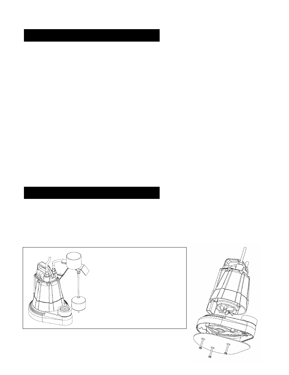
Model S37
has an integrated vertical
float switch. The turn off position can
be adjusted by sliding a rubber
grommet up or down the length of the
float rod.
A.) Removal of the old pump (NOTE: Disconnect pump from power source before handling): Separate the discharge pipe
at either the check valve or at the union. If neither a check valve nor a union is part of the existing discharge pipe, cut the
pipe with a hacksaw and remove the pump (A union or check valve will need to be installed at this cut).
B.) The discharge size is 1-1/2” NPT Do not reduce the discharge size to less than 1-1/4”, as this will affect pump flow and
performance. Schedule 40 PVC pipe is recommended; however, flexible discharge hose kits may be used for temporary
installations.
C.)
Connect the pipe or the discharge hose to the discharge of the pump. HAND TIGHTEN ONLY, over-tightening can damage
the pump discharge.
D.)
Install a union or other means of separating the discharge pipe just above the floor to facilitate removal of the pump if
necessary. A check valve is recommended just above or in place of the union to prevent the back-flow of water
after each pump cycle.
E.) Connect additional pipe as necessary to direct the discharge to the desired location. Discharge should be kept
as short as possible with a minimum number of turns.
F.) Model S37 and S38: When placing the pump in the basin assure that float switch has adequate clearance in pit
and will not interfere with side wall.
G.) For added protection, consider the addition of a back-up pump such as
Liberty’s SJ10 SumpJet, as well as an
alarm such as
Liberty’s ALM-2 in applications where loss of pump function could result in property damage. If
an alarm is used, it must be connected to a separate electrical circuit.
A separate branch circuit, properly fused and grounded, should be provided to the pump. Make sure the power
source is properly sized for the voltage and amperage requirements of the motor as noted on the pump nameplate.
If electrical receptacle is corroded or worn it should be replaced to ensure reliable operation of the pump. The
electrical outlet or panel shall be within the length limitations of the pump power cord and at least 4 feet above floor
level to minimize possible hazards from flood conditions. Check to make sure installation is in accordance with the
National Electric Code and all applicable local codes and ordinances. Wiring extended over greater distances must
be in accordance with NEC requirements. DO NOT USE AN EXTENSION CORD.
3. Installation
ofPInstalla
&hgjhjhgj&Troubl
eshootingTroubleshooting
&Troubleshooting&Troubl
eshooting&Troubleshootin
g&Troubleshooting&Trou
bleshooting
4. Operation
Installa
&hgjhjhgj&Troubles
hootingTroubleshooting&
Troubleshooting&Troubles
hooting&Troubleshooting
&Troubleshooting&Troubl
eshooting