Gorman-Rupp Pumps 06B52-B 1332442 and up User Manual
Page 28
OM-01229
0 SERIES
MAINTENANCE & REPAIR
PAGE E - 9
moved, press the replacement ring into the seal
plate until it seats squarely against the bore shoul
der.
The wear ring must seat squarely in the
seal plate bore or binding and/or exces
sive wear will result.
Subassemble the O‐ring onto the stationary ele
ment and use even pressure to press this subas
sembly into the seal plate until it seats squarely
against the shoulder bore
Carefully slide the assembled seal plate and sta
tionary seal element over the shaft. Use caution not
to nick or damage the stationary seat on the shaft
threads. Secure the seal plate to the pedestal with
the round head machine screws (10).
Subassemble the rotating element into the retainer
and bellows. Lubricate the I.D. of the bellows with
water, and slide this subassembly over the shaft
sleeve until the seal face is just flush with the under
cut end of the sleeve.
Slide the assembled shaft sleeve and rotating por
tion of the seal and onto the shaft until the polished
faces contact. Continue to push the sleeve through
the seal until it is fully seated against the shaft
shoulder.
Install the seal spring.
Impeller Installation
Inspect the impeller and replace it if cracked or
badly worn.
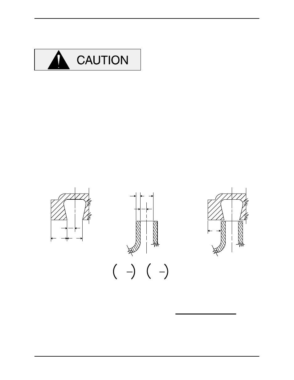
For maximum pump efficiency, the impeller should
be centered within the volute scroll.
To verify the impeller positioning, measure the
pump casing and impeller as shown in Figure 4.
Use these measurements to calculate the required
impeller location (dimension E). Add or remove im
peller adjusting shims (53) until dimension E is ob
tained.
D
B
2
A
B
2
C
D
E
Step 2
Step 1
Step 3
A+
B
2
C+
D
2
E
=
-
Figure 4. Centering Impeller Within Volute Scroll
Install the correct thickness of impeller shims and
install the impeller key (22) in the shaft keyway.
Align the impeller keyway with the key and slide the
impeller onto the shaft until fully seated. Make sure
the seal spring seats squarely over the shoulder on
the back side of the impeller.
NOTE
After the impeller has been properly positioned,
check for free rotation. Correct any scraping bind
ing before further reassembly.
Immobilize the impeller by inserting a bar between
the impeller vanes, being careful not to damage
the vanes. Secure the impeller with the hardware
(39 and 40). Remove the bar from the impeller va
nes.