Gorman-Rupp Pumps 02K11-B 740364 and up User Manual
Page 27
OM-01157
0 SERIES
MAINTENANCE & REPAIR
PAGE E - 8
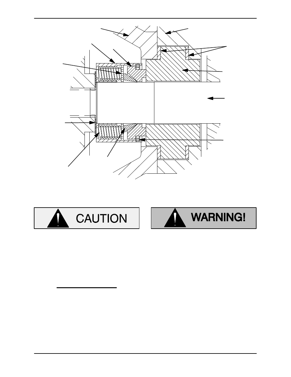
SEAL CAP
IMPELLER
SHAFT
STATIONARY
SEAT
SNAP RING
ROTATING
ELEMENT
IMPELLER
SHIMS
DISC
SPRING
GASKETS
SEALING
WEDGE
INTERMEDIATE
RETAINER
Figure 3. Seal Assembly
This seal is not designed for operation at
temperatures above 160
_F (71_C). Do not
use at higher operating temperatures.
NOTE
The white “Chemlon” stationary seat gasket must
be installed on the seal cavity side of the stationary
seat.
Assemble the stationary seat and gaskets in the
seal cap (24) and secure to them to the intermedi
ate with the hardware (12 and 13).
Slide the assembled intermediate and stationary
portion of the seal over the impeller shaft (19) and
secure the intermediate to the bearing housing
(15) with the previously removed hardware (9, 10
and 11).
New seal assemblies may be equipped
with spring holding clips for storage
purposes. Remove and discard these
clips before proceeding with seal reas
sembly. When removing the clips, use
caution so that they do not pop off
abruptly and cause personal injury. Fail
ure to remove these clips can result in
seal failure and pump damage.
A new seal assembly may be furnished with re
straining clips which keep the wedge from being
compressed prior to assembly. Remove and dis
card the seal spring restraining clips.
Lubricate the I.D. of the wedge and rotating ele
ment with water or a very small amount of oil, and
slide the rotating portion of the seal assembly onto
the shaft until the seal faces contact.