Gorman-Rupp Pumps 82E52-B 1327232 and up User Manual
Page 12
80 SERIES
OM−00825
PAGE B − 6
INSTALLATION
When the pump shuts down, the spring returns the
diaphragm to its original position. Any solids that
may have accumulated in the diaphragm chamber
settle to the bottom and are flushed out during the
next priming cycle.
NOTE
The valve will remain open if the pump does not
reach its designed capacity or head. Valve closing
pressure is dependent upon the discharge head of
the pump at full capacity. The range of the valve
closing pressure is established by the tension rate
of the spring as ordered from the factory. Valve clos-
ing pressure can be further adjusted to the exact
system requirements by moving the spring retain-
ing pin up or down the plunger rod to increase or
decrease tension on the spring. Contact your Gor-
man-Rupp distributor or the Gorman-Rupp Com-
pany for information about an Automatic Air Re-
lease Valve for your specific application.
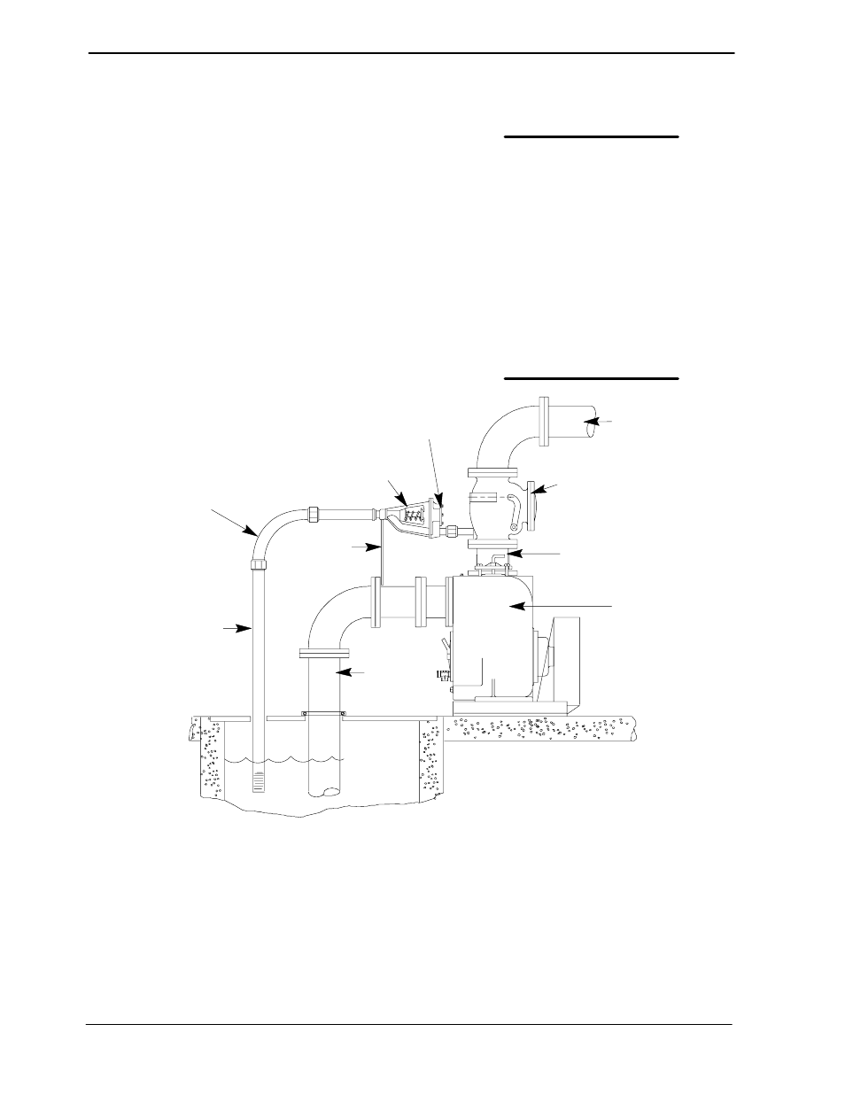
Air Release Valve Installation
The Automatic Air Release Valve must be inde-
pendently mounted in a horizontal position and
connected to the discharge line of the self-priming
centrifugal pump (see Figure 5).
NOTE
If the Air Release Valve is to be installed on a staged
pump application, position the air release valve as
close as possible to the discharge check valve.
DISCHARGE PIPE
DISCHARGE
CHECK VALVE
PUMP DISCHARGE
SELF-PRIMING
CENTRIFUGAL
PUMP
SUCTION
LINE
SUPPORT
BRACKET
CLEAN-OUT
COVER
INSTALL AIR RELEASE VALVE
IN HORIZONTAL POSITION
90
_ LONG
RADIUS
ELBOW
WET WELL
OR SUMP
BLEED LINE 1"
(25,4 MM) DIA. MIN.
(CUSTOMER FUR-
NISHED) EXTEND 6"
(152 MM) BELOW
PUMP OFF LIQUID
LEVEL
Figure 5. Typical Automatic Air Release Valve Installation
The valve inlet line must be installed between the
pump discharge port and the non-pressurized side
of the discharge check valve. The valve inlet is at
the large end of the valve body, and is provided
with standard 1-inch NPT pipe threads.
The valve outlet is located at the opposite end of
the valve, and is also equipped with standard
1-inch NPT pipe threads. The outlet should be con-
nected to a bleed line which slopes back to the wet
well or sump. The bleed line must be the same size
as the inlet piping, or larger. If piping is used for the
bleed line, avoid the use of elbows whenever pos-
sible.
NOTE
It is recommended that each Air Release Valve be
fitted with an independent bleeder line directed