Gorman-Rupp Pumps 13A22-B 1063371 and up User Manual
Page 28
OM-00633
10 SERIES
MAINTENANCE & REPAIR
PAGE E - 5
rate the check valve assembly from the check valve
seat.
Inspect the check valve parts for wear or damage.
If replacement is required, remove the hardware
(63 and 64), and separate the check valve gasket
(61) and weights (60 and 62).
If no further disassembly is required, see Suction
Check Valve Installation.
Back Cover Removal
The wear plate (43) is easily accessible and may be
serviced by removing the back cover assembly
(48). Loosen the clamp bar screw (53) and remove
the clamp bar (54). Pull the back cover and wear
plate from the pump casing. Remove the back cov
er gasket (47). Clean the mating surfaces of the
back cover plate and pump casing.
Inspect the wear plate and replace it if badly scored
or worn. To remove the wear plate, disengage the
hardware (44 and 45) securing it to the back cover.
If no further disassembly is required, see Back
Cover Installation.
Pump Casing Removal
To service the impeller (2), wear plate assembly
(43) and seal assembly (3), disconnect the dis
charge piping. Remove the hardware securing the
pump casing (1) to the base. Disconnect the power
source. Tie and tag any leveling shims used under
the pump mounting feet to ease reassembly.
Remove the nuts (38) securing the pump casing
and gasket set (40) to the pedestal (22) and seal
plate (39). Separate the casing from the seal plate
and pedestal.
Remove the gasket set (40) from the pedestal and
seal plate. Clean the mating surfaces of the seal
plate and pump casing. Tie and tag the gaskets, or
measure and record their thickness for ease of
reassembly. Tie and tag any leveling shims used
under the casing mounting feet to ease reassemb
ly.
Impeller Removal
Before removing the impeller, remove the bottle oil
er and piping (13, 14 and 15). Remove the seal
drain plug (36) and drain the oil from the seal cavity
to prevent the oil from escaping when the impeller
is removed. Clean and reinstall the drain plug.
Immobilize the impeller by wedging a block wood
between the vanes. If removed, install the shaft key
(29). Install a lathe dog on the drive end of the shaft
(30) with the “V” notch positioned over the shaft
keyway.
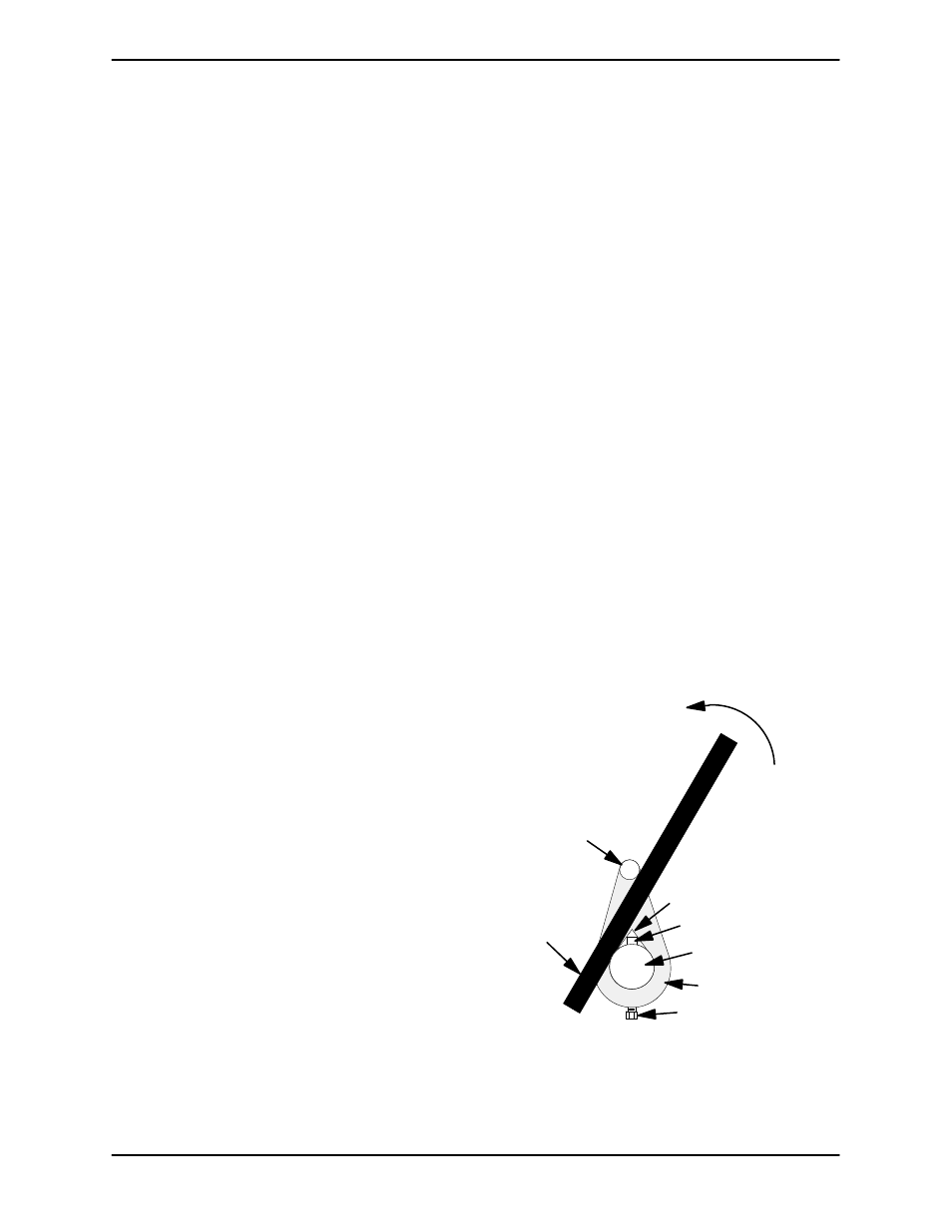
With the impeller rotation still blocked, strike the
lathe dog sharply in a counterclockwise direction
(when facing the drive end of the shaft). The impel
ler may also be loosened by using a long piece of
heavy bar stock to pry against the arm of the lathe
dog in a counterclockwise direction (when facing
the drive end of the shaft) as shown in Figure 2.
Use caution not to damage the shaft or keyway.
When the impeller breaks loose, remove the lathe
dog and wood block and unscrew the impeller
from the shaft.
Turn
Counterclockwise
Lathe Dog Arm
“V” Notch
Shaft Key
Impeller Shaft
Lathe Dog
Setscrew
Heavy
Bar Stock
Figure 2. Loosening Impeller