Gorman-Rupp Pumps 16C2-F4L 1237525 thru 1319250 User Manual
Page 34
10 SERIES
OM−00725
MAINTENANCE & REPAIR
PAGE E − 10
tation is rough or the bearing balls are discolored,
replace the bearings.
The bearing tolerances provide a tight press fit
onto the shaft and a snug slip fit into the intermedi-
ate. Replace the bearings, shaft, or intermediate if
the proper bearing fit is not achieved.
If bearing replacement is required, use a bearing
puller to remove the inboard and outboard bear-
ings (45 and 47) from the shaft.
Shaft and Bearing Reassembly and Installation
(Figure 2)
Inspect the shaft for distortion, nicks or scratches,
or for thread damage on the impeller end. Dress
small nicks and burrs with a fine file or emery cloth.
Replace the shaft if defective.
Position the inboard oil seal (50) in the intermediate
housing bore with the lip positioned as shown in
Figure 2. Press the oil seal into the housing until the
face is just flush with the machined surface on the
housing.
Clean and inspect the bearings as indicated in
Shaft And Bearing Removal And Disassembly.
To prevent damage during removal from
the shaft, it is recommended that bearings
be cleaned and inspected in place. It is
strongly recommended that the bearings
be replaced any time the shaft and bear-
ings are removed.
The bearings may be heated to ease installation.
An induction heater, hot oil bath, electric oven, or
hot plate may be used to heat the bearings. Bear-
ings should never be heated with a direct flame or
directly on a hot plate.
NOTE
If a hot oil bath is used to heat the bearings, both the
oil and the container must be absolutely clean. If
the oil has been previously used, it must be thor-
oughly filtered.
Heat the bearings to a uniform temperature no
higher than 250
_F (120_C), and slide the bearings
onto the shaft, one at a time, until they are fully
seated. This should be done quickly, in one con-
tinuous motion, to prevent the bearings from cool-
ing and sticking on the shaft.
NOTE
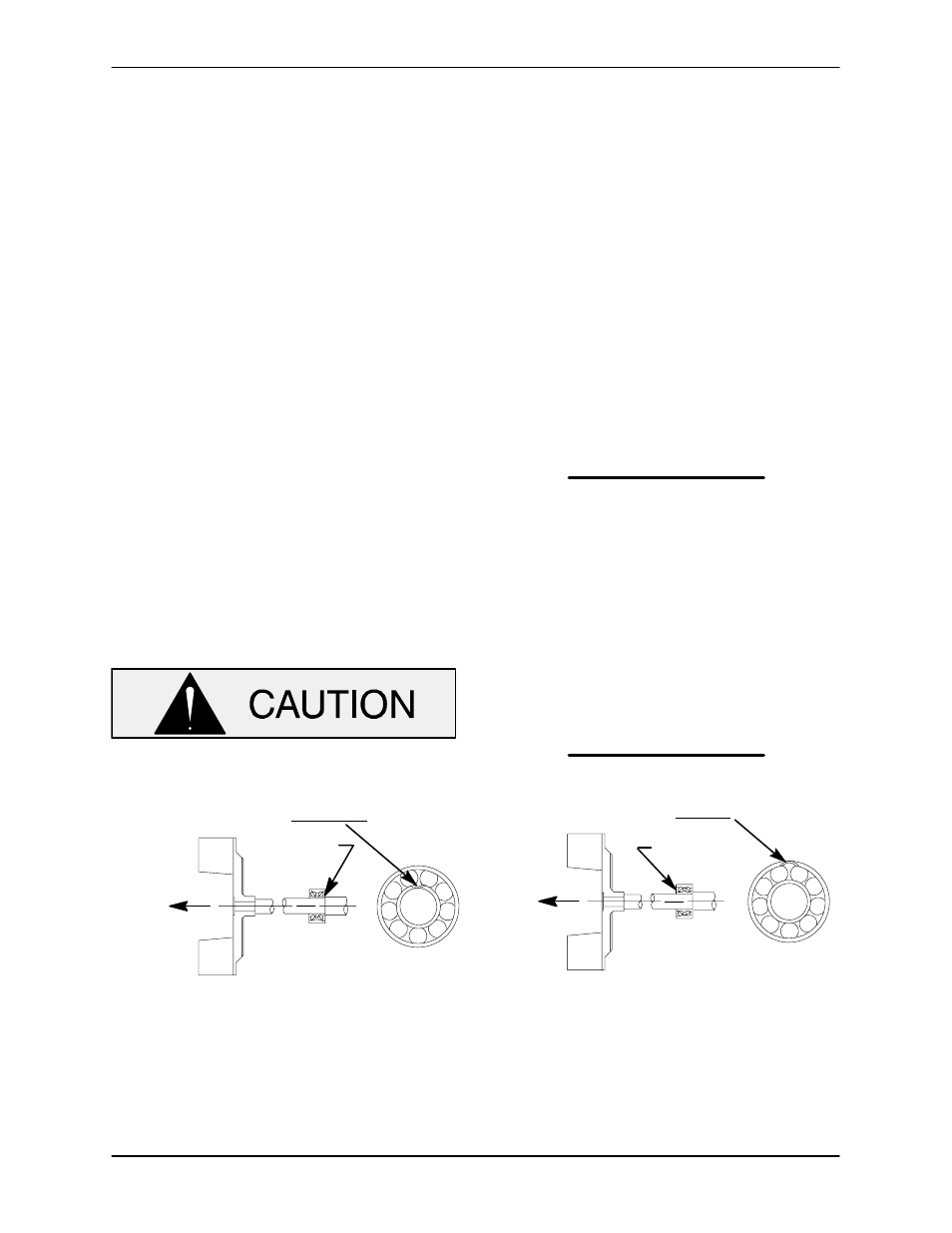
Position the inboard bearing (47) on the shaft as in-
dicated in Figure 4.
INSTALLATION OF NEW DEPARTURE OR
BCA/FEDERAL MOGAL 5300W SERIES BEARINGS
(OPEN OR ENCLOSED IMPELLERS)
INSTALLATION OF MRC/SKF 5300M OR
FAFNIR 5300W SERIES BEARINGS
(OPEN OR ENCLOSED IMPELLERS)
LOADING
DIRECTION OF
THRUST
BALL LOADING
GROOVE POSITIONED
AWAY FROM IMPELLER
GROOVE
DIRECTION OF
THRUST
LOADING
BALL LOADING
GROOVE POSITIONED
TOWARD IMPELLER
GROOVE
Figure 4. Inboard Bearing Positioning
After the bearings have been installed and allowed
to cool, check to ensure that they have not moved
away from the shaft shoulders in shrinking. If
movement has occurred, use a suitable sized
sleeve and a press to reposition the bearings
against the shaft shoulders.