Figure 3. bearing installation – Gorman-Rupp Pumps 810A2-F6L All serial numbers User Manual
Page 28
OM−02754
80 SERIES
MAINTENANCE & REPAIR
PAGE E − 9
Inspect the shaft for distortion, nicks or scratches,
or for thread damage on the impeller end. Dress
small nicks and burrs with a fine file or emery cloth.
Replace the shaft if defective.
The bearings (31 and 33) may be heated to ease
installation. An induction heater, hot oil bath, elec-
tric oven, or hot plate may be used to heat the bear-
ings. Bearings should never be heated with a di-
rect flame or directly on a hot plate.
NOTE
If a hot oil bath is used to heat the bearings, both the
oil and the container must be absolutely clean. If
the oil has been previously used, it must be thor-
oughly filtered.
Heat the bearings to a uniform temperature no
higher than 250
_F (120_C), and slide the bearings
onto the shaft, one at a time, until they are fully
seated. This should be done quickly, in one con-
tinuous motion, to prevent the bearings from cool-
ing and sticking on the shaft.
Use caution when handling hot bear-
ings to prevent burns.
NOTE
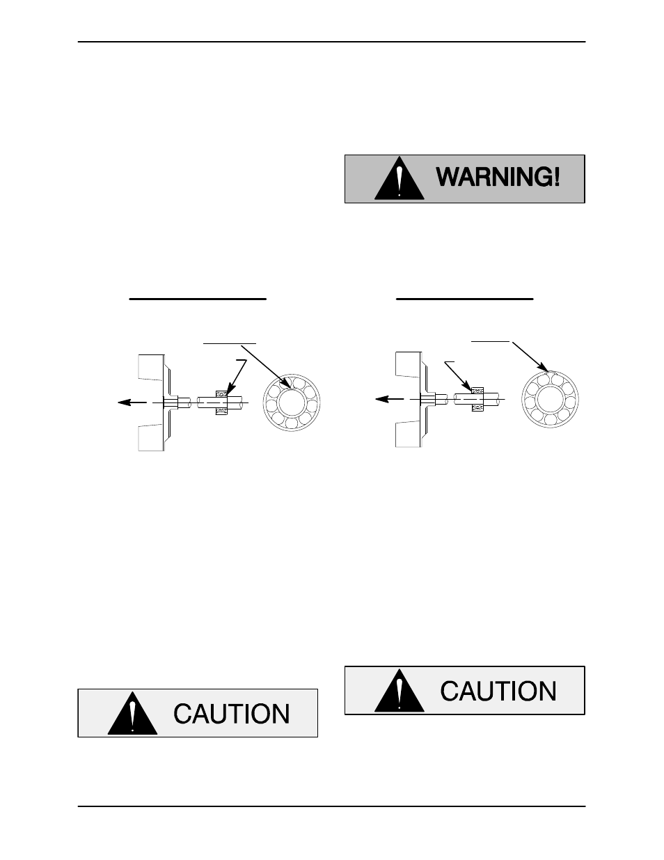
Position the bearing (33) on the shaft as indicated
by the following illustrations.
INSTALLATION OF NEW DEPARTURE OR
BCA/FEDERAL MOGAL 5300W SERIES BEARINGS
(OPEN OR ENCLOSED IMPELLERS)
INSTALLATION OF MRC/SKF 5300M OR
FAFNIR 5300W SERIES BEARINGS
(OPEN OR ENCLOSED IMPELLERS)
LOADING
DIRECTION OF
THRUST
BALL LOADING
GROOVE POSITIONED
AWAY FROM IMPELLER
GROOVE
DIRECTION OF
THRUST
LOADING
BALL LOADING
GROOVE POSITIONED
TOWARD IMPELLER
GROOVE
Figure 3. Bearing Installation
After the bearings have been installed and allowed
to cool, check to ensure that they have not moved
out of position in shrinking. If movement has oc-
curred, use a suitably sized sleeve and a press to
reposition the bearings.
If heating the bearings is not practical, use a suit-
ably sized sleeve and an arbor (or hydraulic) press
to install them on the shaft.
When installing the shaft and bearings
onto the shaft, never press or hit against
the outer race, balls, or ball cage. Press
only on the inner race.
Press the inboard oil seal (34) into the intermediate
(19) with the lip positioned as shown in Figure 2.
Slide the shaft and assembled bearings into the in-
termediate bore from the drive end until the in-
board bearing (33) is fully seated against the bore
shoulder. Be careful not to damage the oil seal lip
on the shaft threads.
When installing the shaft and bearings into
the bearing bore, push against the outer
race. Never hit the balls or ball cage.
Install the outboard oil seal (30) in the bearing cap
(24) with the lip positioned as shown in Figure 2.