Gorman-Rupp Pumps T8A60S-4045H 1514489 and up User Manual
Page 43
OM-06522
SUPER T SERIES
MAINTENANCE & REPAIR
PAGE E - 16
Press the oil seal into the bearing housing until the
face of the seal is just flush with the machined sur
face on the bearing housing.
Press the oil seal (7B) into the drive flange (19) with
the lip positioned as shown in Figure 4. Lightly lu
bricate the flange O‐ring (20) install it in the groove
in the flange, and secure the flange to the bearing
housing with the hardware (17 and 18). Be careful
not to damage the oil seal lip on the shaft keyway.
Lubricate the bearing housing as indicated in LU
BRICATION.
Seal Installation
(Figures 4, 7, 8 and 9)
Most cleaning solvents are toxic and
flammable. Use them only in a well ven
tilated area free from excessive heat,
sparks, and flame. Read and follow all
precautions printed on solvent contain
ers.
Clean the seal cavity and shaft with a cloth soaked
in fresh cleaning solvent. Inspect the stationary
seat bore in the seal plate for dirt, nicks and burrs,
and remove any that exist. The stationary seat bore
must be completely clean before installing the
seal.
A new seal assembly should be installed
any time the old seal is removed from the
pump. Wear patterns on the finished faces
cannot be realigned during reassembly.
Reusing an old seal could result in prema
ture failure.
To ease installation of the seal, lubricate the shaft
sleeve O‐ring (4) and the external stationary seat
O‐ring with a very small amount of light lubricating
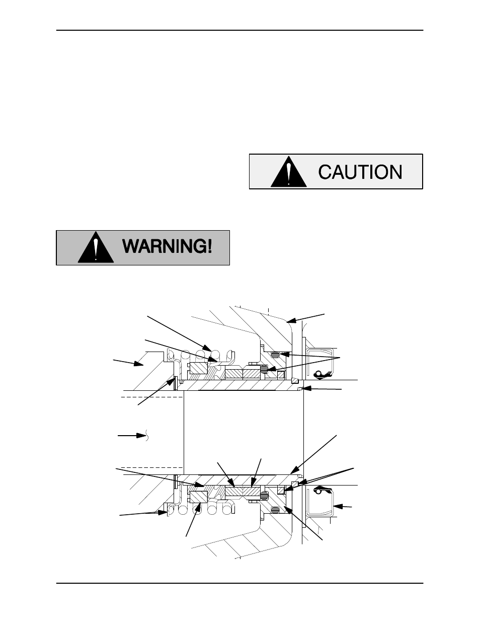
oil. See Figure 7 for seal part identification.
SEAL PLATE
O‐RINGS
IMPELLER
SHAFT
STATIONARY
SEAT
STATIONARY
ELEMENT
ROTATING
ELEMENT
DRIVE BAND
BELLOWS
IMPELLER
SHIMS
IMPELLER
SPRING
RETAINER
INTEGRAL
SHAFT
SLEEVE
SLEEVE
O‐RING
SPRING
CENTERING
WASHER
SHEAR
RING
(SHEARED)
OIL SEAL
Figure 7. Cartridge Seal Assembly