Gorman-Rupp Pumps 83A1-L100EE-X 1512373 and up User Manual
Page 26
OM-05133
80 SERIES
MAINTENANCE & REPAIR
PAGE E - 8
shorten seal life. If necessary, clean the faces with a
non‐oil based solvent and a clean, lint‐free tissue.
Wipe lightly in a concentric pattern to avoid
scratching the faces.
Inspect the seal components for wear, scoring,
grooves, and other damage that might cause leak
age. If any components are worn, replace the com
plete seal; never mix old and new seal parts.
If a replacement seal is being used, remove it from
the container and inspect the precision finished
faces to ensure that they are free of any foreign
matter. Discard the spring centering washer in
cluded with the seal. It is not used in this applica
tion (see Figure 3).
To ease installation of the seal, lubricate the bel
lows, sleeve and O‐ring with water or a very small
amount of light lubricating oil, and apply a drop of
light lubricating oil on the finished faces. Assemble
the seal as follows, (see Figure 3).
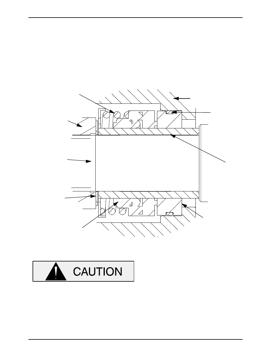
INTERMEDIATE
O‐RING
ENGINE
CRANKSHAFT
STATIONARY
SEAT
BELLOWS
IMPELLER
SHIMS
IMPELLER
SPRING
SHAFT
SLEEVE
Figure 3. Seal Assembly
This seal is not designed for operation at
temperatures above 160
_F (71_C) Howev
er most petroleum products such as gaso
line are more efficiently handled at ambient
temperatures. Do not use at higher operat
ing temperatures.
If the intermediate (12) was removed, lay it on a flat
surface with the impeller side facing up.
Subassemble the O‐ring onto the stationary seat
and press this subassembly into the intermediate
bore until it seats squarely against the shoulder.
Slide the assembled intermediate and stationary
seat over the shaft and secure the intermediate to
the engine with the hardware (10 and 11). When in
stalling the intermediate, use caution not to dam
age the stationary seat on the shaft threads.
NOTE
If the intermediate was not separated from the en
gine during disassembly, subassemble the O‐ring
into the stationary seat and use a piece of plastic