Manual, Level transmitter as signal amplifier – Xylem MJK 713 Open Channel Flowmeter User Manual
Page 14
14
Manual
US 3.10 713 Flow Converter 1210 - Sw 833062
MJK North America, Inc.
37 Sherwood Terrace, #126
Lake Bluff, Il 60044
Tel.: 847-482-8655
Fax: 847-482-8654
[email protected]
www.mjk.com
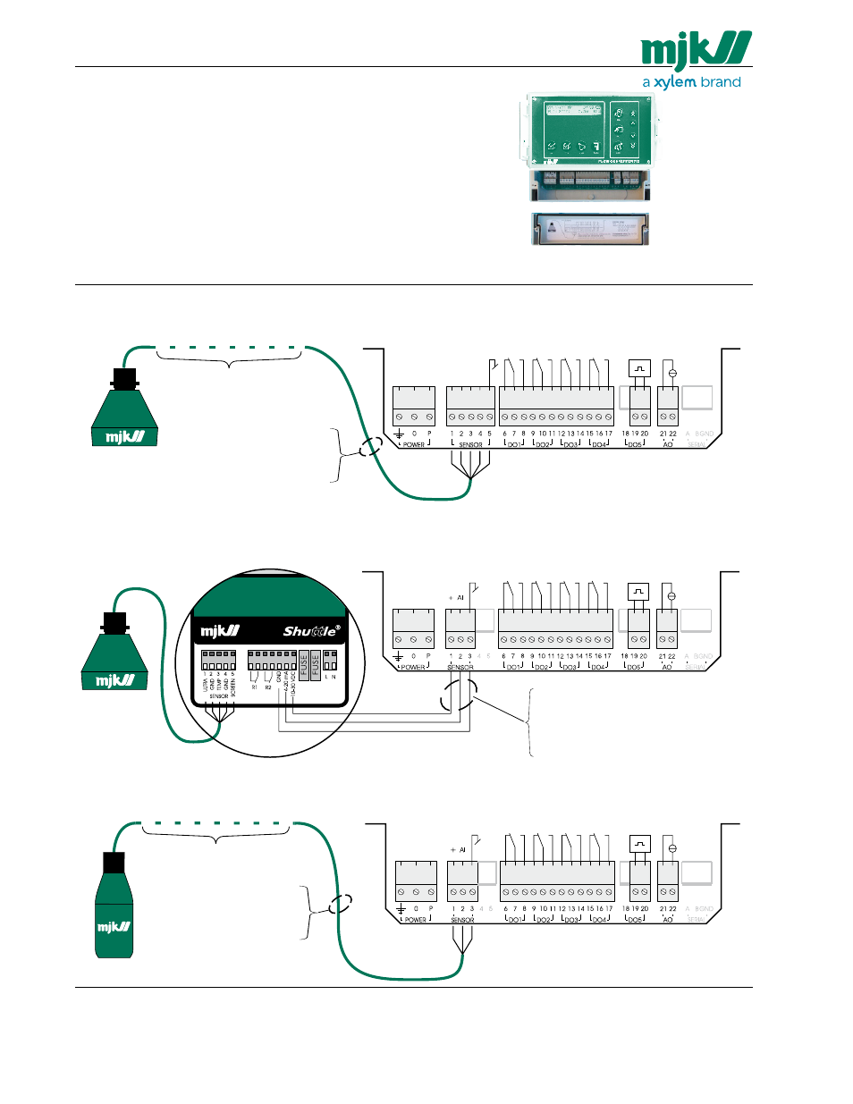
Electrical mounting
MJK 713 must not be connected to the power supply
before the ultrasonic sensor / pressure transmitter is
mounted and connected correctly.
MJK 713 is supplied from the mains on terminal
“0” and “P”.
Current regulations for conductor and fuse dimensions
should always be observed.
Remove the lid to gain access to the terminals.
Relay out 1
Relay out 2
Relay out 3
Relay out 4
Power
supply
Curr
ent output
(0 / 4 - 20 mA)
Totalizer output
Standard cable length 40 ft.
(Can be extended to max.150 ft. using
MJK no. 690010 cable.
No. 1 = brown
No. 2 = red
No. 3 = orange
No. 4 = yellow
No. 5 = black
MJK 713 2500 Flowmeter
Ultrasonic Sensor
MJK 713 System Package 1
MJK 713 2500 with ultrasonic sensor
MJK 713 System Package 3
MJK 713 3000 with hydrostatic level transmitter
Note: 1: Conduit hubs are to beconnected to the
conduit prior to the connection to the enclosure.
2: Terminal tightening torque = 0.5 Nm.
By looping the 4-20 mA signal through one of the relay
outputs on the Shuttle
®
Level Transmitter, a system
failure on the Shuttle
®
Level Transmitter will trig a
system failure message on the MJK 713. Note that
the Shuttle
®
must be programmed as described in
appendix E in order to achieve this function.
Ultrasonic Sensor
MJK 713 3000 Flowmeter
Shuttle
®
Level Transmitter
Power
supply
MJK 713 System Package 2
MJK 713 3000 with ultrasonic sensor using Shuttle
®
Level Transmitter as signal amplifier
Power
supply
No. 1 = red
No. 2 = brown
No. 3 = black
Pressure Transmitter