Manual – Xylem Expert MJK 1100-2100-3100 User Manual
Page 4
Manual
M275US0205
MJK Automation A/S
Byageren 7
DK-2850 Nærum
Denmark
Tel.: (+45) 45 56 06 56
Fax: (+45) 45 56 06 46
[email protected]
www.mjk.com
Electrical mounting
The pressure transmitters are delivered with
39 ft of cable as standard (except 209940
and 209960: 120 ft).
The cable can be lengthened with any type
of cable using connection box 202922.
Although the measuring signal is not sen-
sitive to electrical noise, we recommend
the use of a screened cable.
Ensure that no moisture can enter the
pressure compensation tube inside the cable.
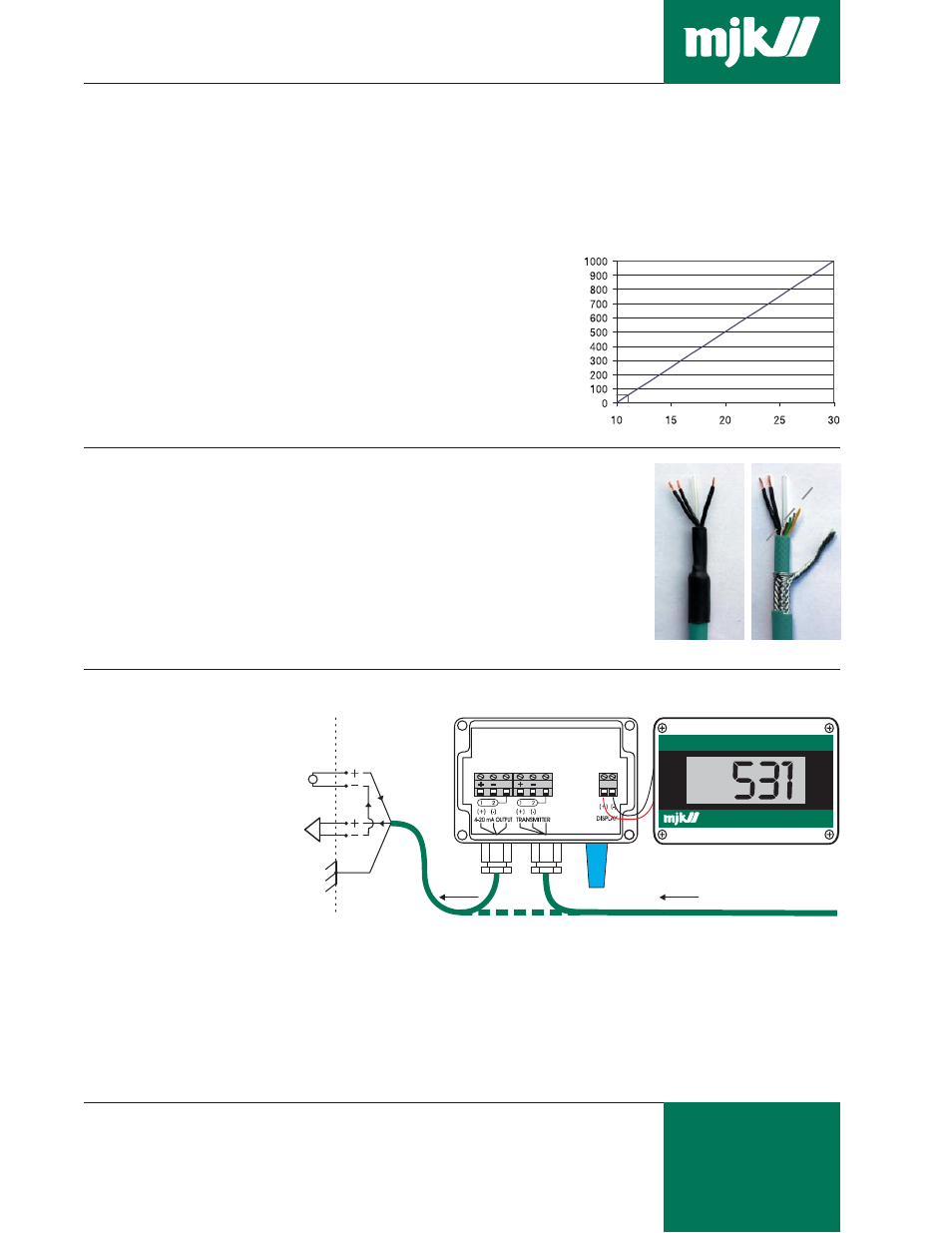
The length of the cable is only limited by
the total resistance (A) of the cable wires +
the input impedance of the analog input on
the MJK 704, MJK 713, PLC etc. (typically 10
to 100
Ω
) and the available supply voltage
(B) (typically 24 V DC).
Example:
The nominal resistance for 1 wire in a
transmitter cable is 0.011
Ω
Ω
Ω
Ω
Ω
/ft. A standard
39 ft cable will therefore add 2 x 0.011 x 39 =
From pressure transmitter
MJK type 531 Field Indicator, order no.
200126 (option, replaces lid for connection
box). See separate data sheet.
MJK Connection Box (NEMA 4X) with
vent plug, order no. 202922.
To ULC,
PLC etc.
Analog input on 704, PLC etc.
(A)
T
otal loop r
esistance [
Ω
]
(B) Supply voltage [V DC]
0.86
Ω
Ω
Ω
Ω
Ω
to the loop resistance. If the analog
input has an impedance of 50
Ω
, the total
resistance will be approx. 51
Ω
Ω
Ω
Ω
Ω
.
According to the diagram below, approx.
12 V DC will be sufficient.
Necessary supply voltage in relation to
the total loop resistance.
Designation of wires,
cutting & stripping the
cable
The factory delivered cable has the wires
marked with the numbers 1 - 2 - 3 as to
the table to the right. If the cable needs to
be cutted and stripped, the shield should
be connected as the no. 3 wire.
Do NOT connect any of the colored program-
ming wires as it may damage the transmit-
ter. The programming wires should be cut off
in different lengths to prevent them from short
circuit. Take care not to block or squeeze
the air pressure compensation tube
➃
➃
➃
➃
➃
.
Cable connection
Wire designation:
1: Positive (+) wire
2: Negative (-) wire
3: Shield
(NOT signal
ground!)
4: Air pressure
compensation
tube
5: Programming
wires
➁
➀
➃
➂
➄
➁
➀
➃ ➂
Factory delivery.
Cutted and stripped.
➁
➀
Positive (+)
wire
➂
Shield
(NOT signal
ground!)
➀
Negative (-)
wire
Power
supply
(10 - 30
V DC)
Analog
input
➀ ➁ ➂ ➀ ➁ ➂