Xylem WMP101-Series ELECTROMAGNETIC FLOWMETERS User Manual
Page 4
FLOW RANGE, INSTALLATION
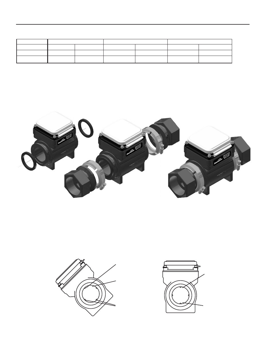
Step 1.
Position gasket
at either end
Step 2.
Place adapter
against gasket,
open screw clamps
to clear flanges
Step 3.
Place screw-clamps
over both adapter
and meter flanges
and tighten screws
INSTALLATION
Piping Conditions.
Installing the meter with a length of
straight pipe at least two times the diameter upstream and
one diameters downstream is highly recommended. Some
piping conditions require more than this. See chart for rec-
ommendations.
End Connections.
The meter comes with Banjo™ union-type
flange connections for ease in servicing the meter. To con-
nect these to piping ends, a variety of kits are available from
any Banjo dealer or from Seametrics.
Follow the diagram below to make the connections.
Position.
This is an all position meter which can be installed either vertically or horizontally, register up, down or angled. How-
ever, entrained air or solids may make some positions preferable to others. See the position diagram for guidance.
Less Ideal:
Air bubbles and sediment on the
electrodes can affect accuracy
Intermittent air
bubbles
pass over
electrode
Possible
sediment
build-up
Recommended:
May prevent sediment
or bubble problems
Electrode
moved from
top by rotating
meter
Intermittent air
bubbles
miss electrode
Electrodes free
from sediment
build-up
WMP
WMP
3
FLOW RANGE
NOTE:
Above installation instructions are for WMP101/104-200 (2”) and WMP101/104-300 (3”) only. The WMP101/104-
100 (1”) is provided with intergrated NPT female threaded ends.
1” 2” 3”
Gal/Min
Liter/Sec
Gal/Min
Liter/Sec Gal/Min Liter/Sec
2.3
.145
6 .38 14 .88
110
6.94
300 18.9 670 42.3
Minimum
Maximum