Remove the coupling, Remove the bearing frame and impeller assembly – Xylem P2001406B Series e-1510 Centrifugal Pumps User Manual
Page 29
1
2
3
4
5
6
12
10
9
8
7
11
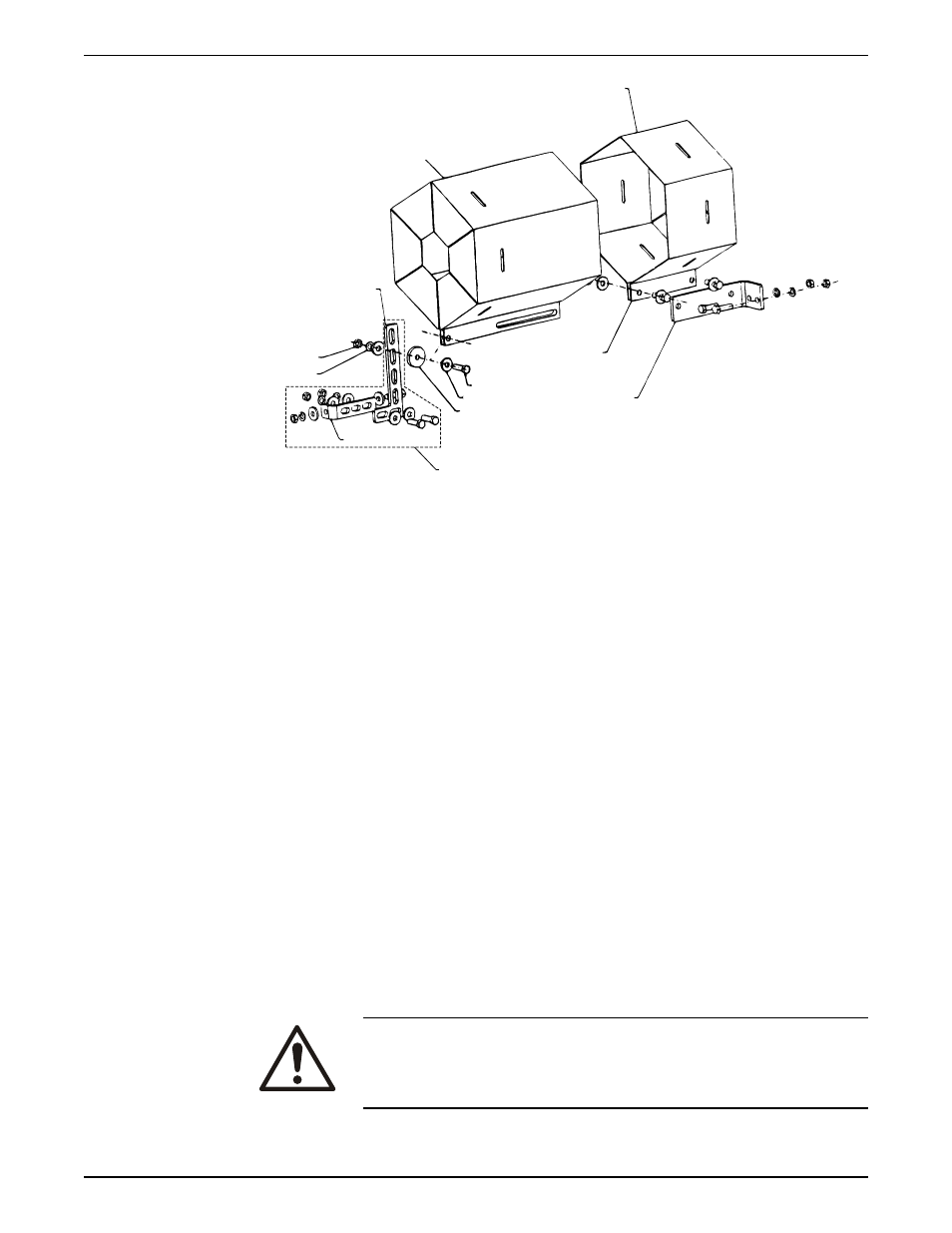
1.
Outer guard
2.
Inner guard
3.
Attach the support bracket inline with the bolt
4.
Support bracket
5.
Nut
6.
Lockwasher
7.
Capscrew
8.
Flat washer
9.
Spacer washer
10. Option used instead of the spacer where overall guard length exceeds 12 in. (30 cm) or
the guard width is over 10 in. (25 cm) across the flats
11. Locate the support arm between the outer guard ends. Align the arm with holes in the
outer guard and holes in the saddle bracket.
12. Motor saddle bracket attached to the motor saddle
Figure 5: Hex guard exploded view for typical installation
Remove the coupling
1. Loosen the setscrews in both coupling halves.
2. Slide each half as far back as possible on the shaft.
3. Remove the sleeve.
If you use a full-diameter impeller, you might have to remove the pump-side coupler half
and slide the motor back on its base. This allows you to gain sufficient clearance in order
to remove the pump assembly from the volute.
Remove the bearing frame and impeller assembly
1. Remove the support foot capscrews.
2. Loosen the volute capscrews but do not remove them.
3. Use the capscrews in the jackscrew holes.
4. Loosen the bearing frame and impeller assembly from the volute.
WARNING:
Make certain that the internal pressure of the pump is relieved before
you continue. Failure to follow these instructions could result in serious
personal injury or death, or property damage.
5. Remove the seal flush piping if it is used.
Maintenance
Series e-1510 Installation, Operation, and Maintenance Manual
27