Xylem IM 16 Seal-less Centrifugal Canned Motor Pumps For Instant Hot Water Recirculating System (obsolete) User Manual
Page 4
4
UltraCirc Models
The UC and UCT-303/353 models incorporate a shut off valve and check valve into the brass pump
housing eliminating the need to install these components. Models with a 01 designation have a
built-in air bleeder valve. These models are supplied with 1/2” (5/8”) union fittings. These fittings
should be removed from the pump housing before soldering to avoid damaging the internal valves.
For SM(T) - 909/959 Models
This unit may be installed into the pipe system without disassembling the pump. However, it is
recommended that the motor section be disassembled from the pump housing by removing the two
pump housing screws so that the system may be flushed as noted in paragraph 9.
For SM(T) - 909/959 Models
This unit may be installed into the pipe system without disassembling the pump. However, it is
recommended that the motor section be disassembled from the pump housing by removing the two
pump housing screws so that the system may be flushed as noted in paragraph 9.
Shut-Off Valve (allows isolation of water in the tank in the event of pump servicing). Hose Bib/
Connection (allows venting of air from system at start-up). Auto Air Vent (allows continuous venting
of air bubbles that intrude into all hot water circulating systems during operation).
8. Close the shut-off valve on the inlet side of the pump and turn the water supply back on.
9. Flush system of debris. Before reattaching the pump motor, open the
shut-off valve on the inlet side of the pump housing and let water flow
through the housing. Use a bucket to catch the water. Let the water run
long enough to clear all sand, solder pellets, plumbers tape flakes, etc.
from the lines. Close the inlet shut-off valve when finished.
10. Connect the pump motor to the housing. Make sure the rubber
o-ring is in place in the housing and the screw ring is securely hand
tightened (for 303/353 models) or that the top housing screws
are firmly in place and tightened (909/959 models). Open the shut-off
valve or valves and let the water flood the pump housing.
11. Purge air from the supply line. Turn on the faucet/taps or shower
farthest from the water heater. Open the line until you get a good,
steady stream of water without sputter or evidence of air.
12. Purge air from the return line. Connect the pump to the electrical supply. With the pump running,
open the hose bib/connection and let water run until the pump is running quietly and there is no
sputtering or other evidence of air coming from the hose bib. Close the hose bib. UC/UCT-303-01
models have a built-in air bleeder valve, use this valve to purge the return line of air. Your system is
now in operation. Allow a few minutes for instant hot water to recirculate to all of your faucet/taps.
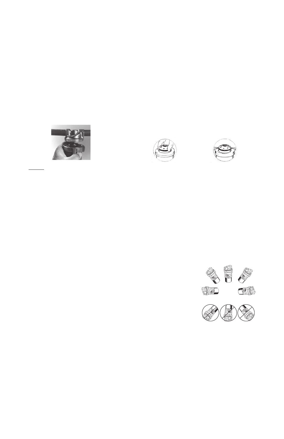
SM-909/1212
SAFETY PRECAUTION: Remove the handle from the hose bib(s)/connection(s) to prevent a small child
from mistaking it for a water faucet/tap. Insulating both the hot water supply and recirculation lines is
strongly recommended.
Fig. 5
303/353 Models - Rotor/Impeller Installation: To remove
the rotor unit, grasp the top of the unit and gently pull
straight up. Do not pull up on one side only or push the
rotor sideways. If the rotor sits too tightly, carefully lever
it off with a screwdriver on each side of the rotor. When
re-installing the rotor, use enough force to hear the rotor
“click” on to the ceramic bearing and spin the rotor with
your fingers to insure that it turns freely.
Fig. 4
Remove the motor unit and o-ring from the pump
housing into the plumbing line. Do not sweat the
housing into the plumbing line with the motor
or o-ring attached. Arrows on the pump housing
indicate the direction of water flow.
Caution: Only hand tighten the screw ring. Do
not over tighten! Do not use plumbers putty on
the screw ring.
Remove the Rotor/ Impeller
by using forefinger and
thumb and pulling upward.
Or, if the Rotor/Impeller cannot
be removed using forefinger and
thumb, carefully lever off evenly
with two screwdrivers.
Correct Installation
Improper Installation
Do NOT mount in these
orientations