Xylem Palmer & Bowlus flumes User Manual
Palmer & bowlus flumes, Installation instructions
Installation Instructions
MJK Automation A/S
Byageren 7
DK-2850 Nærum
Denmark
Tel.: (+45) 45 56 06 56
Fax: (+45) 45 56 06 46
[email protected]
www.mjk.dk
MPBGB0204
As our products are developed continuously,
we reserve the right to make any changes without prior notice.
Palmer & Bowlus flumes
It is very important for the overall measuring
accuracy to comply with the installation
instructions on the next page.
The Palmer & Bowlus flume is characterized
by its circular connection which makes it
easy to install in pipelines.
The flume is aimed at measurement in the
scale of 20 - 100 % of the nominal flow.
No simple formula can be set up for the
Palmer & Bowlus flumes; the formulas are
defined individually for every flume.
General
Flume sizes
Size:
Q
min
Q
max
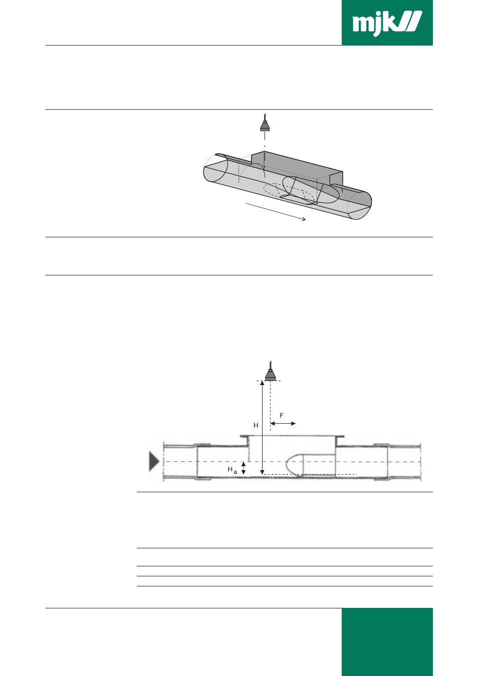
F
H
Ha
Weight
8”
DN 200 (
∅
200 mm)
14 m
3
/h
70 m
3
/h
100 mm
See note
151 mm
2.8 kg
10” DN 250 (
∅
250 mm)
22 m
3
/h
110 m
3
/h
125 mm
below.
179 mm
3.5 kg
12” DN 315 (
∅
315 mm)
40 m
3
/h
200 m
3
/h
150 mm
240 mm
4.8 kg
15” DN 400 (
∅
400 mm)
65 m
3
/h
325 m
3
/h
200 mm
277 mm
9.8 kg
24” DN 600 (
∅
600 mm)
220 m
3
/h
1100 m
3
/h
300 mm
453 mm
15.6 kg
30” DN 800 (
∅
800 mm)
330 m
3
/h
1750 m
3
/h
400 mm
540 mm
30.1 kg
Material:
8”, 10”, 12”:
Glass fibre reinforced polyester / PVC
15”, 24”, 30”: PVC
pH range:
pH 3 - 10
Temperature range:
- 20 … +30 °C, for short periods up to 90 °C
Note: Max. height H must never exceed the measuring range for the flowmeter + deadband.
Note!
For the Palmer & Bowlus flumes with the
dimensions as listed in the table below, the
flow formulas are defined and incorporated
in the flow converter and is chosen in the
menu “Programming of flow calculation”.