Xylem 3101 CONDUCTIVITY CONTROLLER User Manual
Page 5
Global Water
800-876-1172
• globalw.com
- 5 -
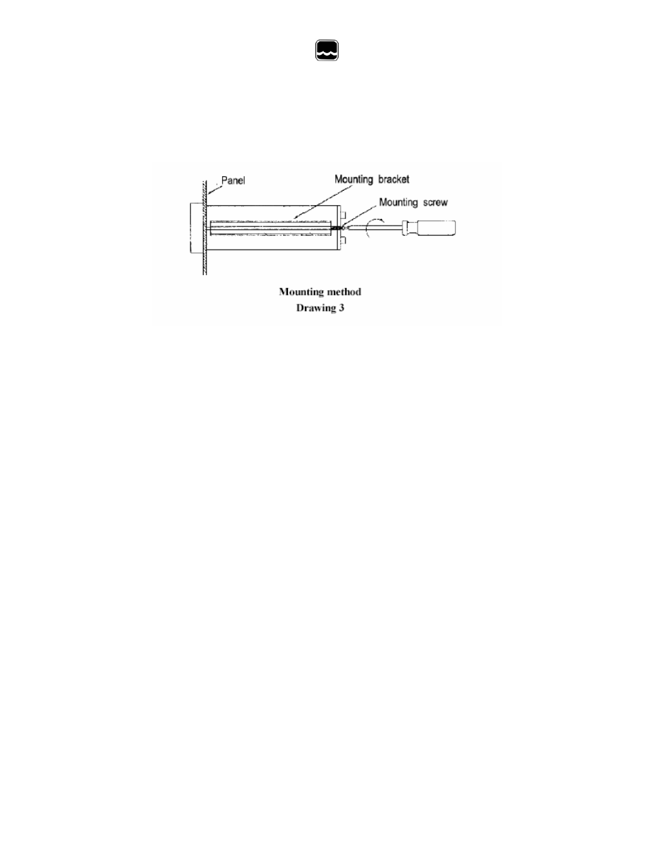
c) Replace the mounting brackets assembly onto the panel meter and fasten the
mounting screws to secure the panel meter to the mounting panel. Refer to
Drawing 3.
IV) Rear Panel Connection Diagram
Refer to Drawing 4 (page 6.)
a) Connect the AC power leads to the terminal strip on the rear of the instrument.
The model 3101 can be used with 115 VAC or230VAC, 50/60 Hz.
b) Connect the two conductivity cell leads from the Cat. No.105 probe to the CELL
terminals on the rear of the instruments.
c) Connect the two temperature compensation leads from the Cat.No.105 probe to
the TH terminals on the rear of the instrument.
d) Connect the load of the high set point relay to the NO and Com of the HIGH SET
terminals on the rear panel.
e) Connect the load of the low set point relay to the NO and COM of the LOW SET
terminals on the rear panel.
V) Earth Ground
a) The EARTH terminal on the rear panel must be connected to ground via third lead
of the power line. Refer to Drawing 4 (Page 6.)
b) If the third lead is not available, use a separate lead to connect the Earth terminal
to ground.
c) This safety procedure must be observed to avoid possible human injury and
damage to devices connected or in contact with the instrument in the event of
instrument failure.