YSI DIQ/S 182 XT-4-MOD User Manual
Page 128
Modbus connection
System 182 XT-4
7 - 12
ba76028e01
02/2012
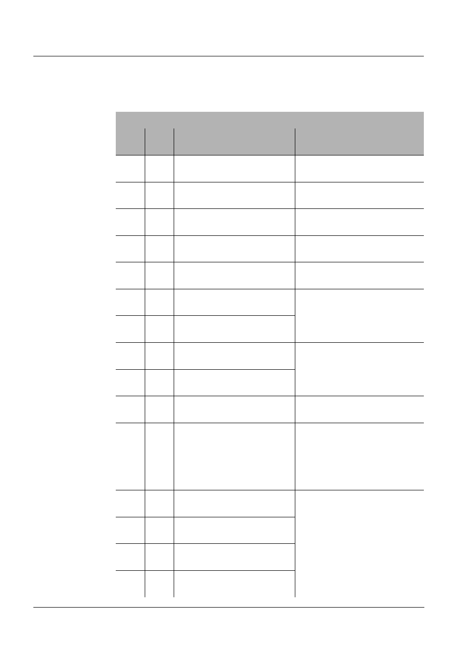
Response with all sensor information of the sensor S02:
Modbus response
Byte
Valu
e
Information
Meaning of the value
1
01h
Modbus address of the DIQ/
S 182 XT-4-MOD
01h --> 1
2
04h
Function
04h --> 4
Read Input Register
3
10h
Number of bytes
10h --> 16
16 Byte (8 registers)
4
02h
Contents of register 9 (HI)
= sensor number
02h (Int 8) --> 2
Sensor number S02
5
02h
Contents of register 9 (LO)
= sensor status
02h (Int 8) --> MEASURE
6
04h
Contents of register 10 (HI)
= sensor model
0401h (Int 16)
--> VisoTurb 700 IQ
7
01h
Contents of register 10 (LO)
= sensor model
8
00h
Contents of register 11 (HI)
= status info
0000h (Int 16)
--> no errors
9
00h
Contents of register 11 (LO)
= status info
10
00h
Contents of register 12 (HI)
= measuring mode
00h (Int 8) --> FNU Turb
11
14h
Contents of register 12 (LO)
= measured value status
14h (Int 8)
Main measured value (bits 7-4):
1h --> VALID
Secondary measured value
(bits 3-0):
4h --> MISSING
12
42h
Contents of register 13 (HI)
= main measured value
429E46C2h (Float 32)
--> 79,1382
Measured parameter and unit,
see byte 10 (measuring mode)
13
9Eh
Contents of register 13 (LO)
= main measured value
14
46h
Contents of register 14 (HI)
= main measured value
15
C2h
Contents of register 14 (LO)
= main measured value