System design – Xylem IM112 AquaBoost 1AB1 & 2AB1 Variable Speed Pump Controllers User Manual
Page 3
3
System Design
System Design
Note
Systems MUST be designed by qualifi ed technicians only and meet all applicable state and local
code requirements.
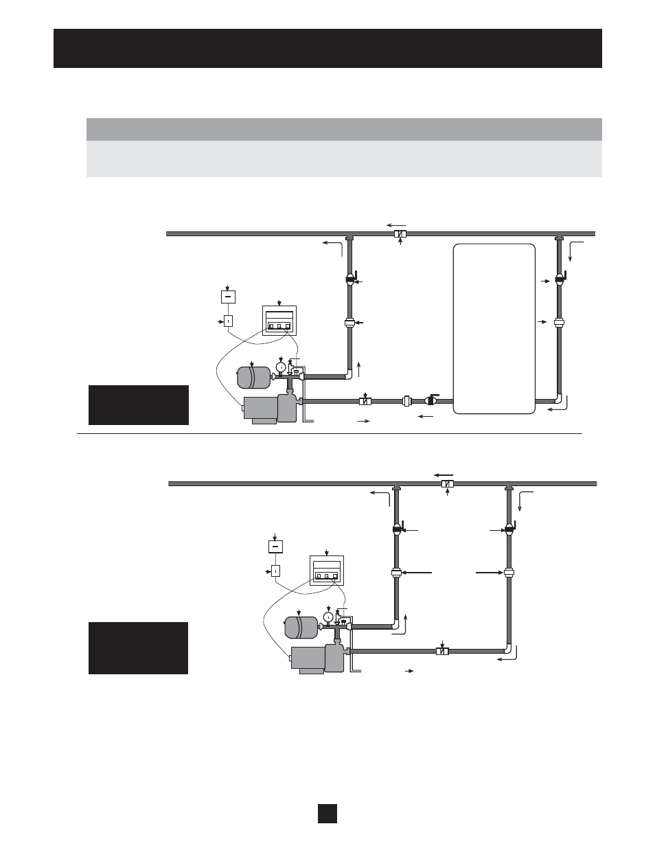
The following diagrams show a typical system using the AquaBoost Controller. Connection can be made directly to
a water supply or water can be drawn from a supply tank. Diagram #1 shows a typical set up for a supply tank.
Diagram #2 shows a set-up for municipal water connection. This allows pump maintenance without main line
shut-off.
A diaphragm pressure tank is used on the discharge side of the pump to maintain pressure in the line when
there is no demand. This will keep the pump from continuing to run. With the AquaBoost Controller, it is not
necessary to have a large tank for supply purposes. In selecting a tank, make sure it can withstand system pres-
sure. The tank should have a capacity of at least 10% of the maximum pump fl ow rate in gpm. Typically, pumps
used with the AquaBoost controller use a V6P or larger Goulds Pumps Hydro-Pro
®
Tank. Pre-charge the tank to
the following:
PSI Set Pressure 15 30 45 60 75
PSI Tank Pre-charge
12 21 37 52 64
Diagram 1
AquaBoost Installation
for Well Pump System
Diagram 2
AquaBoost Installation
for Municipal Water
System
Home Supply
Water Main
Check Valves
Isolation Valve
Unions
Check Valves
To Drain
Relief
Valve
Gauge
Tank
AquaBoost Control
Circuit Breaker
Disconnect
Home Supply
Well Supply
Check Valves
Isolation Valve
Unions
Check Valves
To Drain
Relief
Valve
Gauge
Tank
AquaBoost Control
Circuit Breaker
Disconnect
Atmospheric
Storage Tank