Xylem IM253 R0 AquaStart Combination Soft Starters User Manual
Page 7
7
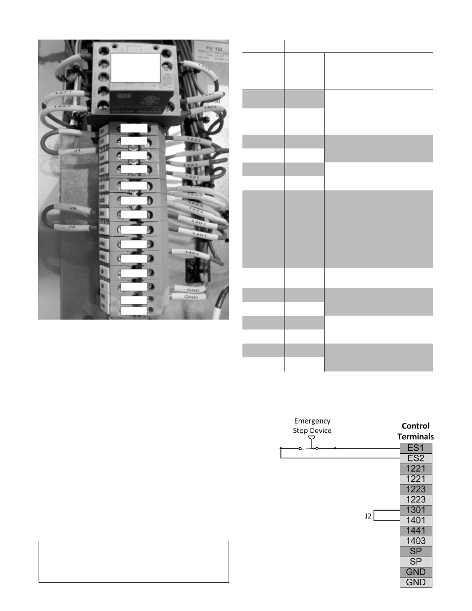
CONTROL WIRING TERMINALS
CONNECTIONS FOR REMOTE START/STOP
* Emergency Stop
A Safety or Emergency Stop function can be implemented
by removing the J1 jumper connecting terminals ES1
and ES2. The emergency stop device will then be wired
between ES1 and ES2. When an emergency situation
(high pressure, high temperature, …) is encountered the
device must open to disconnect control power to the
circuitry enabling the soft starter. This will then stop the
pump/motor. This control device must be sized to operate
at 2.5A at 115Vac.
CAUTION! THE EMERGENCY STOP DEVICE DOES
NOT DISCONNECT LINE POWER TO THE SOFT
STARTER.
FIGURE 4 – Control Wiring Terminals
CONTROL WIRING TERMINAL STRIP
SSW 07
Terminals
Control
Terminal
Label
Control Terminal
Description
ES1
Safety/Emergency Stop*
Connected by J1. To enable an
emergency stop function, re-
move J1 and install the control
device between ES1 and ES2
ES2
A1
1221
110Vac Control Voltage
1221
A2
1223
Neutral for Control Voltage
1223
13
1301
Connected to 1401 by J2.
J2 Enables Start and Stop
Buttons on enclosure cover.
To disable buttons on the cover,
remove J2. To add a remote
Start/Stop, connect a jumper
from 1301 to 1441 and wire the
control device between 1441
and 1403.
1401
Connection to Start and Stop
Buttons on enclosure cover.
1441
Remote Start/Stop**
1403
SP
Spares
SP
GND
Ground
GND
Control Relay
ES1
1221
1301
1401
1441
1403
SP
GND
GND
SP
1221
1223
1223
ES2