Xylem IM229 R06 Aquavar SOLO User Manual
Page 6
6
The lengths in each of the Wire Sizing tables represent 100% of the allowable voltage drop when motor is running at full
load. When sizing wire, the voltage drop of each wire segment must be included. The total must not exceed 100% of the
allowable drop. Take for example a 1.5 HP 3Ø motor with a distance from Service Entrance to Controller of 100' and 500'
between the Controller and Motor.
• Service Entrance to Controller = 100' of 10 AWG (100/455) = 22 % (455' is from the S.E. to Controller chart)
• Controller to Motor
= 500' of 12 AWG (500/709) = 71 % (709' is from the Controller to Motor chart)
Total Drop (must be ≤ 100%) 93 %
If the distance from the Controller to Motor was 600' (600/709) = 85% + 22% = 107%, we would need to use #10 wire
for that segment, ex. 600/1126 = 53% + 22% (for 100' of #10) = 75% which is acceptable. It is also acceptable to use dif-
ferent wire sizes for the Buried and Well sections of wire.
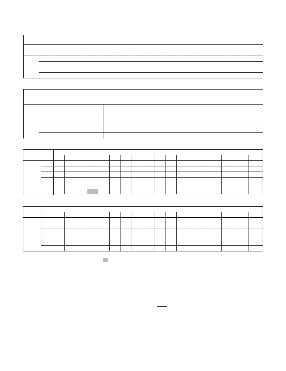
All Models – Service Entrance to Controller
Controller Motor
Copper Wire Size 75ºC Insulation Exposed to a Maximum of 50ºC (122ºF) Ambient Temperature ②
Input
HP 14 12 10 8 6 4 3 2 1 1/0
2/0
3/0
4/0
250
300
350
400 500
¾ 279 445 706 1020 1608 2552 3186 4019 5065 6383 8055
1 226 360 571 824 1300 2064 2576 3250 4095 5161 6513 8201
230V 1½ * 286 455 657 1036 1644 2052 2589 3262 4111 5188 6533 8236 9710
1 PH 2 * * 331 478 754 1197 1495 1886 2376 2995 3779 4759 5999 7073 8455 9852
3 * * 246 355 561 890 1111 1401 1766 2225 2808 3536 4458 5256 6283 7321 8343
5 * * * 218
343 545 680 858 1081 1363 1720 2165 2730 3219 3847 4483 5109 6348
3AS20, 30, 50 Controller to Motor – Controllers with 3Ø Motors
Controller Motor
Copper Wire Size 75ºC Insulation Exposed to a Maximum of 50ºC (122ºF) Ambient Temperature ②
Output
HP 14 12 10 8 6 4 3 2 1 1/0
2/0
3/0
4/0
250
300
350
400 500
¾ 690 1100 1748 2523 3978 6316 7884 9945
1 558 890 1413 2040 3216 5106 6375 8041
230V
1½ 445 709 1126 1625 2562 4068 5078 6406 8072
3 PH
2 324 516 820 1184 1866 2963 3699 4666 5879 7410 9351
3 241 384 609 880 1387 2202 2749 3467 4369 5506 6949 8750
5
* 235 373 539 849 1348 1683 2123 2675 3372 4255 5358 6755 7964 9520
①
Reduce lengths by 13% for 200 V systems.
* Wire does not meet the N.E.C. ampacity requirement.
②
Lengths in bold require 90º C wire.
Shading indicates 40º C maximum ambient.
Table 2: Wire Sizing
Maximum Cable Lengths in Feet to Limit Voltage Drop to 5% for 230 V Systems
①
1AS15 Controller to Motor – Controllers with 2-Wire 1Ø Motors
Motor Lead Lengths - CentriPro 2-Wire Motors -
Based on Service Factor Amps, 30º C Ambient and 5% Voltage Drop
Motor Rating
60º C & 75º C Insulation - AWG Copper Wire Size
Volts
HP kW SFA 14 12 10 8 6 4 2 1/0 2/0 3/0 4/0
½ 0.37 4.7 466 742 1183 1874 2915 4648 7379 11733 14803 18688 23544
230
¾ 0.55 6.4 342 545 869 1376 2141 3413 5419 8617 10871 13724 17290
1
0.75
9.1
241
383
611
968
1506
2400
3811
6060
7646
9652
12160
1½ 1.1 11.0 199 317 505 801 1246 1986 3153 5013 6325 7985 10060
1AS15 Controller to Motor – Controllers with 3-Wire 1Ø Motors
Motor Lead Lengths - CentriPro 3-Wire Motors (CSIR) -
Based on Service Factor Amps, 30º C Ambient and 5% Voltage Drop
Motor Rating
60º C & 75º C Insulation - AWG Copper Wire Size
Volts
HP kW SFA 14 12 10 8 6 4 2 1/0 2/0 3/0 4/0
½ 0.37 6.3 348 553 883 1398 2175 3467 5505 8753 11044 13942 17564
¾ 0.55 8.3 264 420 670 1061 1651 2632 4178 6644 8383 10582 13332
230
1
0.75
9.7
226
359
573
908
1413
2252
3575
5685
7173
9055
11408
1½ 1.1 11.1 197 314 501 793 1234 1968 3124 4968 6268 7913 9969
2 1.5 12.2 180 286 456 722 1123 1790 2843 4520 5703 7199 9070