Transducer jumper, Insulation and winding resistance tests, Danger – Xylem IM229 R06 Aquavar SOLO User Manual
Page 10: What it means
10
FLOAT SWITCH OPERATION - Filling a Pond or Tank
and Constant Pressure System:
• Connect two wires from a float (level) switch to fill or
empty a tank or pond and a pressurized system. The
maximum switch wire length tested is 200’. The pump
will operate at various speeds and try to maintain the set
point pressure. If piping is large and it cannot maintain
set point pressure it will operate at maximum speed.
• Typical UIB Settings:
• 60 or 80 Hertz (depends on pump/motor)
• Pump Stop – High
• Dry Well - High (switch to low if it trips while pumping)
• Low Pressure Cut-Off - On (switch to off if pressure
drops by 20 PSI or more)
• Pressure Drop - 5 PSI
• Transducer - Connected
• Transducer Jumper - Bottom Position (Factory Setting)
• Float Switch Connected to Switch Input
Transducer Jumper
Explosion Hazard. Keep jumper in bottom
position whenever a pressure transducer is
used. Failure to do so may cause a pressure transducer error
to be ignored and an over-pressure hazard to result.
For applications not requiring a pressure transducer such
as level control, the transducer can be removed. When
the transducer is not used, the Transducer Jumper must be
placed in the top position to prevent a sensor error. Never
place the jumper in the top position when using a pressure
transducer.
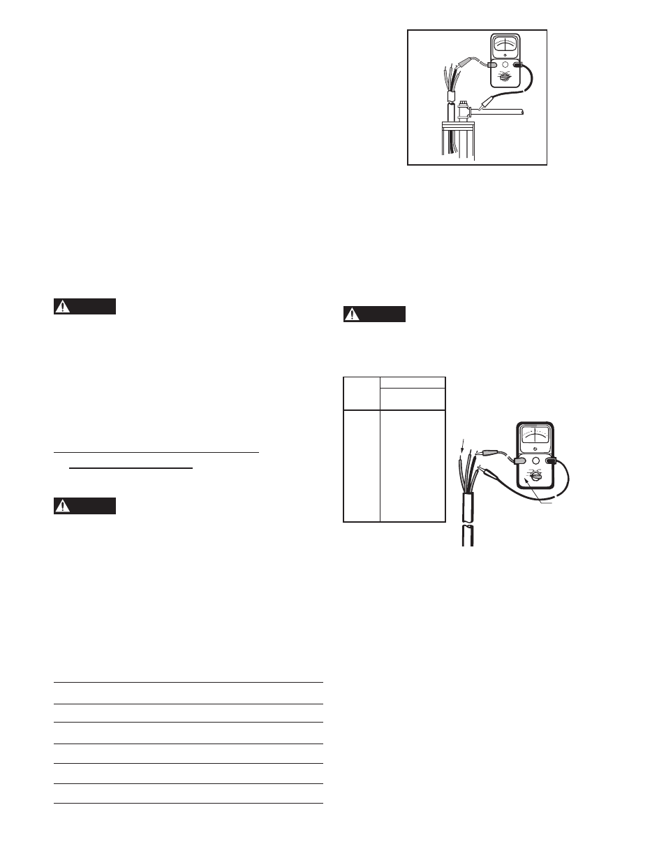
5: INSULATION AND WINDING
RESISTANCE TESTS
INSULATION RESISTANCE
Electrocution Hazard. Turn off power and
wait 5 minutes before opening cover.
1. Set the scale lever to R x 100K and adjust to 0.
2. Disconnect motor leads from controller (note position
of wires). Connect an ohmmeter lead to any one of the
motor leads and the other to the metal drop pipe. If the
drop pipe is plastic, connect the ohmmeter lead to the
metal well casing or ground wire.
Normal Ohm and Megohm Values (Insulation
Resistance) Between All Leads and Ground
Insulation resistance does not vary with rating. All motors of all
HP, voltage and phase rating have similar values of insulation
resistance.
Condition of Motor and Leads
Ohms
Megohm
Value Value
A new motor (without drop cable).
20,000,000
20.0
(or more)
A used motor which can be
10,000,000
10.0
reinstalled in the well.
(or more)
New motor in the well
2,000,000
2.0
(or more)
(or more)
Motor in the well in good condition
500,000 –
2,000,000
0.5 – 2.0
Insulation damage, locate and repair
Less than
Less than
500,000 .50
DANGER
DANGER
DANGER
What it Means
1. If the ohm value is normal, the motor windings are not grounded
and the cable insulation is not damaged.
2. If the ohm value is below normal, either the windings are grounded or
the cable insulation is damaged. Check the cable at the well seal as the
insulation is sometimes damaged by being pinched.
MOTOR WINDING RESISTANCE CHECKOUT
1. Set the scale lever to R x 1 for values under 10 ohms. For values
over 10 ohms, set the scale lever to R x 10. Zero balance the
ohmmeter.
Electrocution Hazard. Turn off power and
wait 5 minutes before opening cover.
2. Connect the ohmmeter leads as shown below.
Cable Resistance – Copper
See motor data pages for motor resistance ratings.
What it Means
1. If all ohm values are normal, the motor windings are neither shorted
nor open, and the cable colors are correct.
2. If any one ohm value is less than normal, the motor is shorted.
3. If any one ohm value is greater than normal, the winding or the cable is
open or there is a poor cable joint or connection.
4. If some ohm values are greater than normal and some less and the
motor is single phase with red, black and yellow wires, then the leads
are mixed.
Z E R O
O H M S
R X 1 0 0
R X 1 0
R X 1
R X 1 0 0 0
R X 1 0 K
R X 1 0 0 K
O H M S
RX1
or
RX10
Motor
Leads
Ground
Wire
If aluminum cable is used the readings
will be higher. Divide the ohm readings
on this chart by 0.61 to determine the
actual resistance of aluminum cable.
Size
Paired Wire
Cable Resistance
(ohms per foot)
14
.0050
12
.0032
10
.0020
8 .0013
6 .0008
4 .0005
2 .0003
0 .0002
00
.00015
000
.00013
0000
.00010
5: INSULATION AND WINDING
RESISTANCE TESTS
OHMS
R x 1000
R x 10K
R x 100K
R x 100
R x 10
R x 1
ZERO
OHMS
R x 100K
Drop
Cable
with
Ground
Wire