Xylem IM247 R02 SPD PLUS Centrifugal Pump Controller Quick Start Guide User Manual
Spd plus, Centrifugal pump controller quick start guide, Quickstart guide
SPD PLUS
Centrifugal Pump Controller
Quick Start Guide
Overview
The installation of the SPD PLUS adjust-able
speed drive follows the outline below.
Task
PREPARE for installation
UNPACK the drive
PREPARE mounting location
REMOVE the front cover
MOUNT the drive
INSTALL wiring
CHECK installation
REINSTALL the cover
APPLY power
START-UP Assistant
Application
This guide provides a quick reference for
installing SPD PLUS drives having a standard
enclosure (NEMA 1).
NOTE: This guide does not provide detailed
installation, safety or operational instruc-
tions. See the Installation Operation Manual
for complete information.
Prepare for Installation
WARNING! The Aquavar should ONLY
be installed by a qualified electrician.
Check
• Motor Compatibility – Motor type, nominal current,
frequency and voltage range must match drive
specifications (3 phase motor only).
• Suitable Environment – Drive requires heated,
indoor controlled environment that is suitable for
the selected enclosure below 122º F (50º C).
• Wiring – Follow local codes for wiring and fusing
requirements. Refer to NEC, Local, State or Munici-
pal codes.
Refer to the Installation Operation Manual and
confirm that all preparations are complete.
Tools Required
Screwdrivers, wire stripper, tape measure, mount-
ing screws or bolts, and drill.
Use the following chart to interpret the type code
found on the drive label.
Collect Motor Data
Collect the following data from the motor nameplate
for later use in the Aquavar startup:
• Voltage ______________________________
• Nominal Motor Current _______________
• Nominal Frequency ___________________
• Nominal Speed ______________________
• Nominal Power _______________________
Unpack the Drive
NOTE: Lift the SPD PLUS by its chassis and not
by its cover.
1. Unpack the drive.
2. Check for any damage and notify the
shipper immediately if damaged com-
ponents are found.
3. Check the contents against the order
and the shipping label to verify that all
parts have been received.
Prepare the Mounting Location
The drive requires a smooth,
vertical, solid surface, free from
heat and moisture, with free
space for air flow – 200 mm (8
in.) above and below, and 25
mm (1 in.) around the sides of
the drive.
1. Mark the mounting
points.
2. Drill the mounting holes.
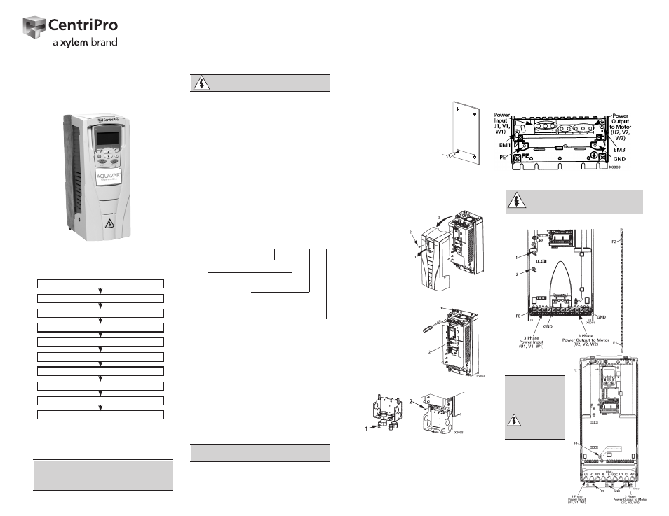
Remove the Front Cover
1. Remove the control panel
(display), if attached.
2. Loosen the
captive screw
at
the top.
3. Pull near the
top to remove
the cover.
Mount the Drive
1. Position the
SPD PLUS and use
screws or bolts to
securely tighten all
four corners.
2. Attach a warning
sticker in the
appropriate lan-
guage on the inside
plastic shell.
Install the Wiring
(copper only)
1. Install thin-wall conduit clamps (not
supplied) in the conduit/gland box.
2. Install conduit/gland box.
Wiring Power
1. Connect conduit runs to box.
2. Route input power and motor
wiring through conduits.
1
X0002
SPD 4 0600 N1
Single Pump Drive
Voltage
2 – 230 Volt
4 – 460 Volt
5 – 575 Volt
Nominal Horsepower
0400 = 40 HP 0500 = 50 HP 0600 = 60 HP
0750 = 75 HP 1000 = 100 HP
Enclosure and Filter Options
Blank = NEMA 3R, no filter N1 = NEMA 1, no filter
F = NEMA 3R, with filter
NOTE: HP rating is for reference only, and is based on 3Ø input power.
3. Strip wires.
4. Connect power, motor and
ground wires to the drive terminals.
See “Power Supply and Wiring”
in the instruction manual.
Frame Sizes R1…R4
* Single phase input power must use U1, W1
and PE for wiring.
WARNING! For floating networks
remove screws at EM1 and EM3 on
Frame Sizes R1…R4.
Frame Size R5
Frame Size R6
WARNING!
For floating net-
works remove
screws at
F1 and F2
on Frame
Sizes R5 or R6.
QUICKSTART GUIDE
IM247R02