Technical data, Frequency of starts, Mounting position – Xylem IM103 R03 5 and Larger Submersible Pump User Manual
Page 11: Motor cooling, temperature and time ratings
11
Technical Data
(Continued)
Technical Data
Transformer Capacity Required for Submersible
Motors – Single or Three Phase
Distribution transformers must be adequately sized to satisfy
the KVA requirements of the submersible motor. When
transformers are too small to supply the load, there is a
reduction in voltage to the motor.
Table 1 references the motor horsepower rating, single
phase and three phase, total effective KVA required, and the
smallest transformer required for open or closed three phase
systems. Open systems require larger transformers since only
two transformers are used.
Other loads would add directly to the KVA sizing require-
ments of the transformer bank.
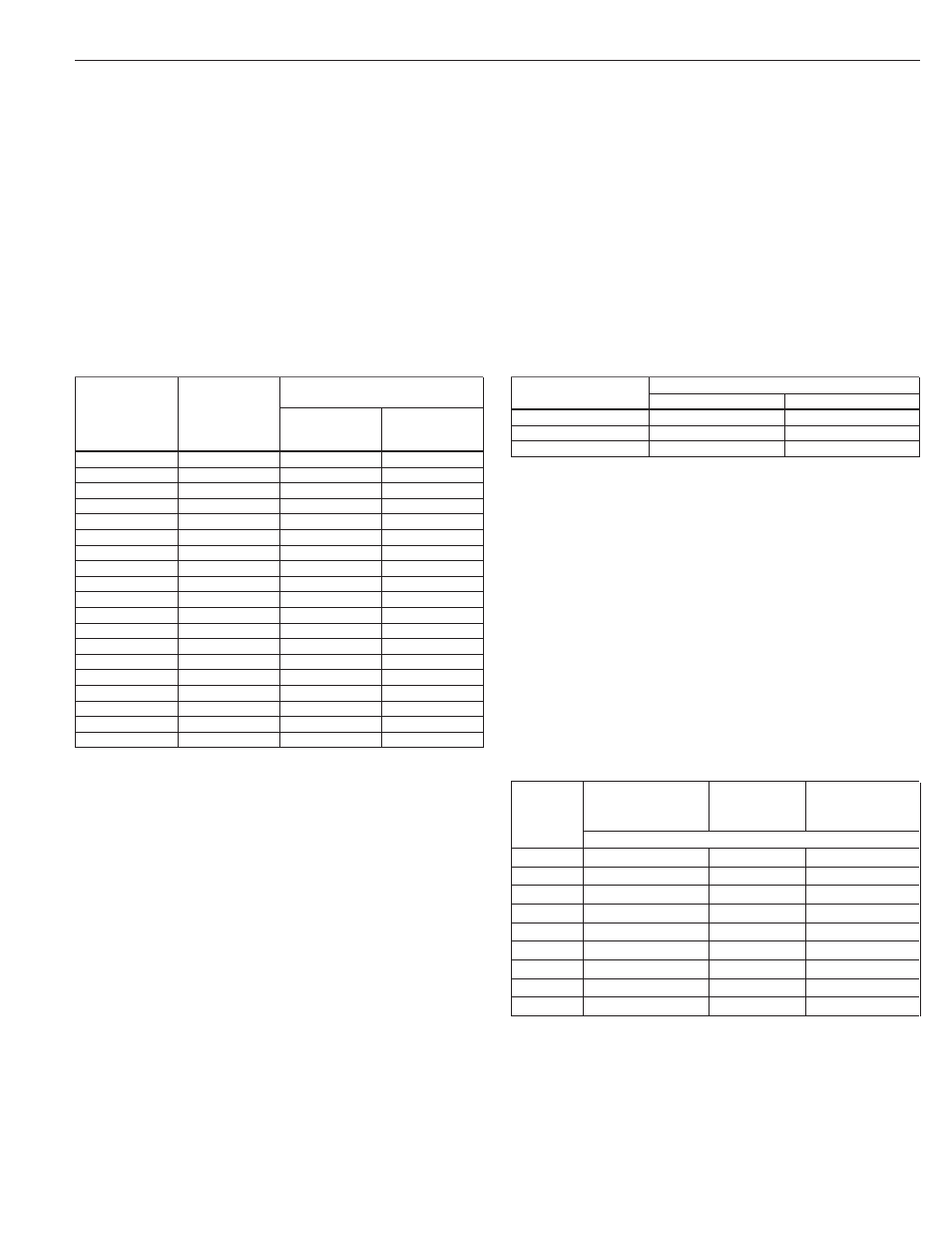
Table 1 – Transformer Capacity
Smallest KVA Rating –
Each Transformers
Motor HP
Open WYE
Closed
Total Effective
or DELTA
WYE or DELTA
KVA Required 2 Transformers 3 Transformers
1½
3
2
1
2
4
2
1.5
3
5
3
2
5
7.5
5
3
7½
10
7.5
5
10
15
10
5
15
20
15
7.5
20
25
15
10
25
30
20
10
30
40
25
15
40
50
30
20
50
60
35
20
60
75
40
25
75
90
50
30
100
120
65
40
125
150
85
50
150
175
100
60
175
200
115
70
200
230
130
75
NOTE: Transformers shown are standard nominal KVA ratings. If power company experience
and practice allows transformer loading higher than nominal rating under the specific operat-
ing conditions and maintains correct voltage and balance, such higher loading values may be
used for transformer(s) to meet total effective KVA required.
Table 2 – Number of Starts
Maximum Starts per 24 hour day
Motor Rating
Single Phase
Three Phase
½ HP through 5 HP
100
300
7½ HP through 30 HP
50
100
40 HP and over
—
100
Frequency of Starts
The average number of starts per day over a period of
months or years influences the life of a submersible pumping
system. Excessive cycling affects the life of control compo-
nents such as pressure switches, starters, relays and capaci-
tors, plus splines and bearings. Rapid cycling can also cause
motor overheating and winding failures.
The pump size, tank size and other controls should be select-
ed to keep the starts per day as low as practical for longest
life, based upon the maximum number of starts per 24 hour
day, as shown in Table 2.
Motors over 2 HP should be allowed to run a minimum of
2 minutes to dissipate heat build up from starting current.
Mounting Position
Motors are suitable for operation in mounting positions
from vertical shaft up to horizontal. If 4 inch motors through
2 HP are started more than 10 times per day, it is recom-
mended the shaft be tilted up at 15° from horizontal to
minimize coast-down wear of the upthrust washer.
Motor Cooling, Temperature and Time Ratings
All 4 inch CentriPro motors may be operated continuously
in water up to 86º F. Optimum service life will be attained
by maintaining a minimum flow rate past the motor of .25
feet per second. Use a Flow Sleeve if velocity is below the
.25'/sec, if the well is top feeding or when the pump is used
in a large body of water or large tank.
Six (6) inch canned design motors from 5 – 40 HP will
operate in water up to 95º F (35º C), without any de-rating
of horsepower, with a minimum flow rate of .5 ft./sec. past
the motor. 6" – 50 HP and all 8" – 10" motors can operate in
77º F (25º C) water with .5'/sec velocity past the motor.
Table 3 – Minimum Flow Rates For Proper Motor Cooling
Well or
3.75" Diameter
CP = 5.5" Dia. CP = 7.52" Dia.
Sleeve
4" CP or FE Motor
6" CP Motor
8" CP Motor
Diameter
.25'/sec
.5'/sec.
.5'/sec.
(inches)
GPM Required
4
1.2
–
–
5
7
–
–
6
13
7
–
7
20
23
–
8
30
41
9
10
50
85
53
12
80
139
107
14
110
198
170
16
150
276
313
Multiply gpm by .2271 for m
3
/Hr.
Multiply gpm by 3.785 for l/min.