Discharge piping, Rotation, Operation – Xylem IM060 R03 Model MCC User Manual
Page 4: Maintenance, Disassembly
4
3.2. Suction pipe must be at least as large as the suction
connection of the pump. Smaller size will degrade
performance.
3.3. If larger pipe is required, an eccentric pipe reducer
(with straight side up) must be installed at the pump.
3.4. Installation with pump below source of supply:
3.4.1. Install full flow isolation valve in piping for
inspection and maintenance.
Do not use suction isolation valve to
throttle pump.
3.5. Installation with pump above source of supply:
3.5.1. Avoid air pockets. No part of piping should be
higher than pump suction connection. Slope
piping upward from liquid source.
3.5.2. All joints must be airtight.
3.5.3. Foot valve to be used only if necessary for
priming, or to hold prime on intermittent
service.
3.5.4. Suction strainer open area must be at least
triple the pipe area.
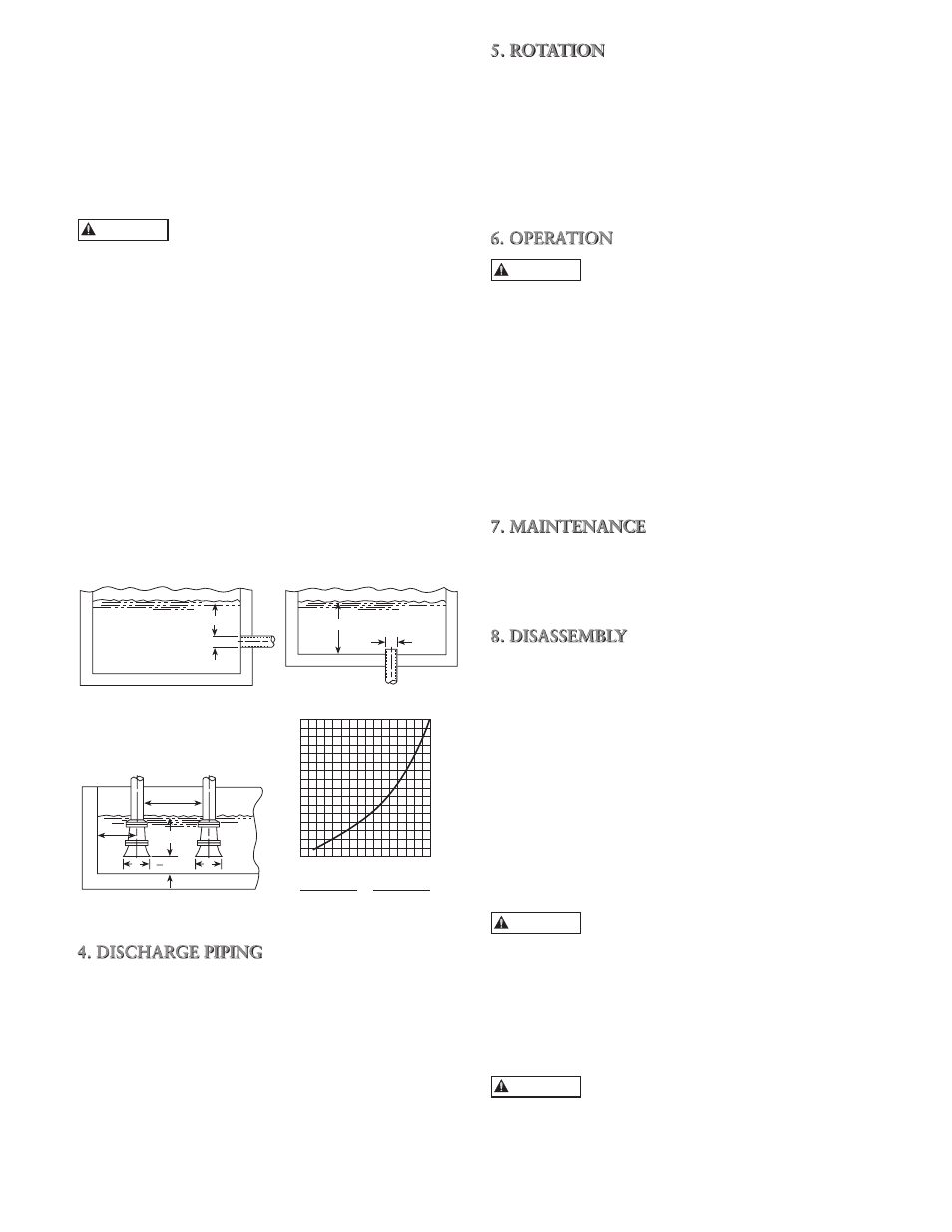
3.6. Size of inlet from liquid source, and minimum
submergence over inlet, must be sufficient to prevent
air entering pump through vortexing. See Figures 1
through 4.
3.7. Use 3 to 4 wraps of Teflon tape to seal threaded con-
nections.
4. DISCHARGE PIPING
4.1. Arrangement must include a check valve located
between a gate valve and the pump. The gate valve
is for regulation of capacity, or for inspection of the
pump or check valve.
4.2. If an increaser is required, place between check valve
and pump.
4.3. Use 3 to 4 wraps of Teflon tape to seal threaded con-
nections.
5. ROTATION
5.1. Correct rotation is right-hand (clockwise when
viewed from the motor end). Switch power on and
off quickly. Observe shaft rotation. To change rota-
tion:
5.1.1. Single-phase motor: Non-reversible
5.1.2. Three-phase motor: Interchange any two
power supply leads.
6. OPERATION
Pumped liquid provides lubrication. If
pump is run dry, rotating parts will seize
and mechanical seal will be damaged. Do not operate
at or near zero flow. Energy imparted to the liquid is
converted into heat. Liquid may flash to vapor. Rotating
parts require liquid to prevent scoring or seizing.
6.1. Before starting, pump must be primed (free of air
and suction pipe full of liquid) and discharge valve
partially open.
6.2. Make complete check after unit is run under operat-
ing conditions and temperature has stabilized. Check
for expansion of piping.
7. MAINTENANCE
7.1. Ball bearings are located in and are part of the mo-
tor. They are permanently lubricated. No greasing
required.
8. DISASSEMBLY
Complete disassembly of the unit will be described. Pro-
ceed only as far as required to perform the maintenance
work required.
8.1. Turn off power.
8.2. Drain system and flush if necessary.
8.3. Remove motor hold-down bolts.
8.4. Disassembly of Liquid End
8.4.1. Remove casing bolts (370).
8.4.2. Remove back pull-out assembly from casing
(100).
8.4.3. Remove impeller locknut (304).
Do not insert screwdriver between impel-
ler vanes to prevent rotation of close-
coupled units. Remove cap at opposite end of motor. A
screwdriver slot or a pair of flats will be exposed. Using
them will prevent impeller damage.
8.4.4. Remove impeller (101) by turning counter-
clockwise when looking at the front of the
pump. Protect hand with rag or glove.
Failure to remove the impeller in a
counter-clockwise direction may damage
threading on the impeller, shaft or both.
8.4.5. With two pry bars 180 degrees apart and
inserted between the seal housing (184) and
the motor adapter (108), carefully separate
H min.
D
D
H min.
D
D
1.5D
min.
3.0D
min.
H min.
D min.
2
16
15
14
13
12
11
10
9
8
7
6
5
4
3
2
1
H = Min. Submergence in feet
H
1 2 3 4 5 6 7 8 9 10111213141516
V
V = Velocity in feet per second
= GPM x 0.321
Area
GPM x 0.4085
D
2
Figure 3
Figure 4
Figure 1
Figure 2
CAUTION
CAUTION
CAUTION
CAUTION