Xylem IM010 R08 Model 3656/3756 User Manual
Page 10
10
11. Apply LOCTITE
®
#271 or equivalent, to new impeller bolt
threads and tighten to:
3
⁄
8
"-16 bolts
20 lbs.-ft. (27 N.m)
½"-13 bolts
38 lbs.-ft. (51 N.m)
Impeller bolt not used for SAE units.
12. For SAE units apply LOCTITE
®
#271 to the external
threads of the shaft and internal threads of the impeller
nut (22). Tighten impeller nut to the following:
½"-Impeller Nut (SAE M-Group) 80 lbs.-ft. (107 N.m)
¾"-Impeller Nut (SAE L-Group) 100 lbs.-ft. (134 N.m)
13. For SAE units, after impeller nut (22) has been installed,
apply
LOCTITE
®
#271 to set screw (22A). Install impeller
set screw into face of impeller nut (22) and tighten
hand-tight.
14. Replace casing wear ring, if removed.
15. Replace casing bolts and tighten, in a crossing sequence,
to torque values indicated below:
3
⁄
8
"-16 bolts (bronze casing)
25 lbs.-ft. (34 N.m)
½"-16 bolts (cast iron casing)
37 lbs.-ft. (50 N.m)
½"-13 bolts (cast iron casing)
90 lbs.-ft. (122 N.m)
¾"-10 bolts (cast iron casing)
175 lbs.-ft. (237 N.m)
16. Check reassembled unit for binding by rotating shaft with
appropriate tool from motor end.
17. If rubbing exists, loosen casing bolts and proceed with
tightening sequence again.
18. Replace motor hold-down bolts and motor end plug or
cover on close-coupled units.
19. Replace coupling, spacer, coupling guard and frame
hold-down bolts on frame-mounted units.
NOTICE: ALWAYS RECHECK BOTH ALIGNMENTS
AFTER MAKING ANY ADJUSTMENTS.
20. Refer to the “COUPLING ALIGNMENT” section of
this manual to realign shaft.
21. Assembly is complete.
Packed Box
1. Make sure stuffing box is free of foreign materials and
clean before beginning packing of packed box. Refer to
Sectional Assembly in the repair parts section.
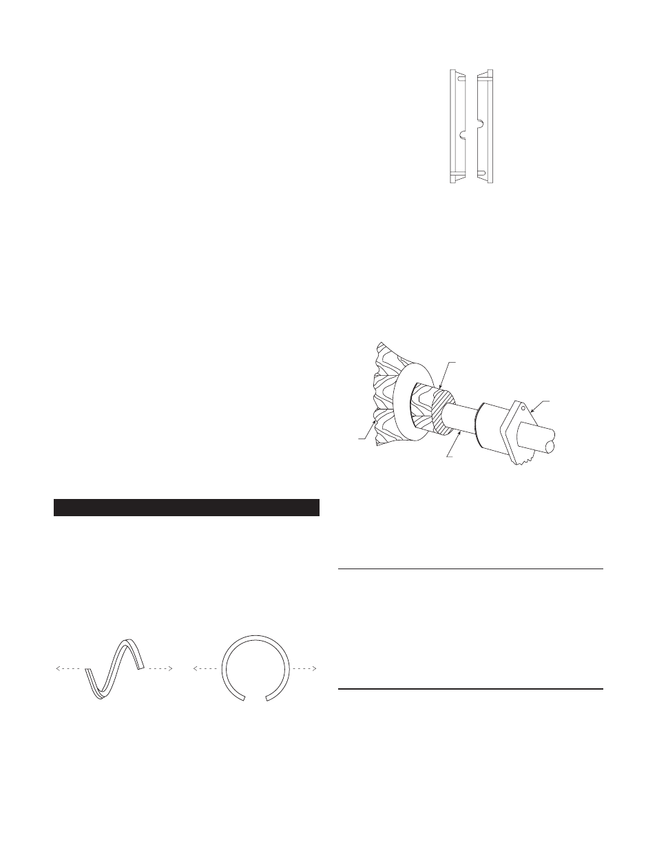
2. Take special care during installation of packing rings
because they are die-formed. To install, twist the ring
sideways just enough to fit it around the shaft sleeve.
DO NOT ATTEMPT TO PULL RINGS STRAIGHT
OUT. See Figure 12.
Figure 12
CORRECT
WRONG
3. Install the two piece Teflon lantern ring supplied as shown
in figure 13. Note: two pieces make one ring. Notches on
ring must face each other, but alignment is not necessary.
4. Install the packing rings and lantern ring in the following
sequence to pack the packed box. Install two rings of
packing, then the lantern ring, followed by the final three
rings of packing. Install each ring separately and firmly
seat. The use of a wooden split bushing is recommended
to accomplish this. See Figure 14. Use gland to jack the
bushing and ring into the box. Stagger joints in each ring
90°. Make sure the flush tap in the packed box lines up
with the center of the lantern ring. Any extra rings are
spares.
5. Tighten gland nuts evenly, but not tight. When the pump
is started, slowly tighten the gland nuts until the leak rate
is between 40 and 60 drops per minute. A grease lubricant
can be used when the pumpage contains abrasive particles
or for a suction lift condition.
REMOVAL OF PACKED BOX
• Follow these steps to remove the packing from the
packed box.
1. Remove gland assembly.
2. With a “packing hook” remove packing.
3. Insert a wire hook into the ring on the outer edge to
remove the lantern ring.
4. Clean the packed box.
PRIME SAFE ARRANGEMENT (Optional – M & L Group Only)
• The Prime Safe arrangement can be provided with grease or
an oiler feed lubrication.
1. The grease gland (24) will have the letters "G" and "O"
stamped on the outside diameter and have two
1
⁄
8
" NPT
connections for mounting a grease feeder or oiler.
Teflon Lantern Ring
Figure 13
Figure 14
STUFFING
BOX
WOODEN “SPLIT BUSHING”
SHAFT
GLAND