Relay outputs, Analog i/o, Digital inputs – Xylem AQCPCQR Aquavar CPC Quick Reference Start-Up Guide User Manual
Page 2
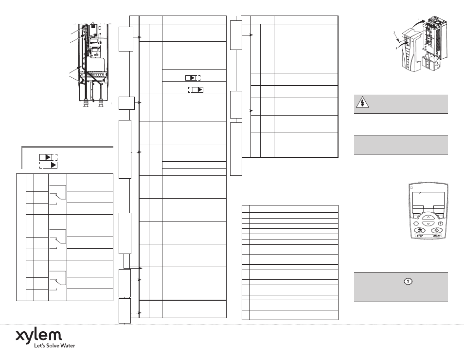
Wiring the Transducer
1. Route the
transducer
cable
through
the conduit.
2. Strip the
transducer
cable
sheathing
and twist
the screen
wire.
3. Connect the screen
wire of the
transducer to
terminal X1-1.
4. Connect the power supply wire of the
transducer (red or brown) to terminal
X1-10.
5. Connect analog output wire from the
transducer (white or black) to X1-5.
See chart in next column.
Note 1. Jumper Setting: (Analog Input)
J1
AI1: 0…10 V
AI2: 0(4)…20 mA
Relay output 1, pro-
19 RO1C
grammable. Default
2
= run power to drive
20 RO1A
Maximum: 250 VAC/
30 VDC, 2 A
21 RO1B
Minimum: 500 mW
(12 V, 10 mA)
Relay output 2, pro-
22 RO2C
grammable. Default
2
= ready, pump is
running
23 RO2A
Maximum: 250 VAC/
30 VDC, 2 A
24 RO2B
Minimum: 500 mW
(12 V, 10 mA)
Relay output 3, pro-
25 RO3C
grammable. Default
2
= not used
26 RO3A
Maximum: 250 VAC/
30 VDC, 2 A
27 RO3B
Minimum: 500 mW
(12 V, 10 mA)
6. Install the conduit/gland box cover (1
screw).
X1
Control Wiring
Digital input common.
To activate a digital input,
there must be ≥+10V
(or
≤-10V) between that
12
DCOM input and DCOM. The 24V
may be provided by the
AQUAVAR (X1-10) or by
an external 12…24V
source of either polarity.
13 DI1 Digital input 1, program-
mable. Default
2
= run enable
14 DI2 Digital input 2, program-
mable. Default
2
= low water
Digital input 3,
15 DI3 programmable. Default
2
= E-stop or jumper
Digital input 4,
16 DI4 programmable. Default
2
= set point selection
17 DI5 Digital input 5, program-
mable. Default
2
= not used
18 DI6 Digital input 6, program-
mable. Default
2
= not used
1
Digital input impedance 1.5 kΩ. Maximum voltage for
digital inputs is 30 V.
2
Default values depend on the macro used. Values
specified are for the default macro, single/multi-pump.
NOTE: Jumper Wires between 3 and 11, 10 and
15, 11 and 12.
Check Installation
Before applying power, perform the following checks.
√
Check
Environment conforms to specifications.
The drive is mounted securely.
Proper cooling space around the drive.
Motor and driven equipment are ready for start.
Floating networks: Internal RFI filter disconnected.
Drive is properly grounded, with pump/motor.
Input power (mains) voltage matches the drive nominal
input voltage.
The input power (mains) terminals, U1, V1, W1, are
connected and tightened as specified.
The input power (mains) fuses / mains switch installed.
The motor terminals, U2, V2, W2, are connected and
tightened as specified.
Motor cable is routed away from other cables.
NO power factor compensation capacitors are connected
to the motor cable.
Control terminals are wired and tightened as specified.
NO tools or foreign objects (such as drill shavings) are
inside the drive.
NO alternate power source for the motor is connected
– no input voltage is applied to the output of the drive.
Reinstall the Cover
1. Align the cover
and slide
it on.
2. Tighten
the captive
screw.
3. Reinstall the
control panel.
Apply Power
Always reinstall the front cover before turn-
ing power on.
WARNING! The AQUAVAR will start
up automatically at power up, if the
external run command is on.
1. Apply input power.
When power is applied to the
AQUAVAR, the green LED comes on.
NOTE! Before increasing motor speed,
check that the motor is running in the
desired direction.
Start-Up
In Start-Up, enter motor data (collected earlier)
and, if needed, edit parameters that define how
the drive operates and communicates.
Wizards
The Start-Up
Wizard steps through
typical start-up selec-
tions and runs auto-
matically upon the initial
power up. At other
times, use the steps be-
low to run the Start-Up
Wizard.
1. Use the MENU key to access the Menu list.
2. Select Wizards.
3. Select Start-Up Wizards.
4. Follow the screen instructions to configure
the system.
NOTE! For common parameters and menu
items, use the Help Key to display
descriptions. If you encounter Alarms or
Faults, use the Help Key or refer to the
Diagnostic section of the instruction manual.
5
3
1
ON
ON
DIR
MENU
REM
11.1%
LOC
REM
40.2 PSI
sp
0.0 PSI
ac
0.0 HZ
R
elay Outputs
10–15
E-stop
or
Jump-
er
Jumper
Wire
ON
ON
X1
Control Wiring
Terminal for transducer
1 SCR shield. (Connected inter-
nally to chassis ground.)
Analog input channel 1,
2nd transducer. Default
2
= frequency reference.
Resolution 0.1%,
2 AI1 accuracy ±1%.
J1:AI1 OFF: 0…10 V (Ri =
312 kΩ)
J1:AI1 ON: 0…20 mA (Ri
= 100 Ω)
Analog input circuit com-
mon. (Connected inter-
3
AGND nally to chassis gnd.
through 1 MW. Jumper
wire to X1-11.)
10 V/10 mA reference
4
+10V
voltage output for analog
input potentiometer,
accuracy ±2%. (Not used.)
Analog input channel 2.
Resolution 0.1%,
5 AI2 accuracy ±1%.
Transducer input
4–20 mA
Analog input circuit com-
6
AGND
mon. (Connected inter-
nally to chassis gnd.
through 1 MΩ)
Analog output, program-
7
AO1
mable. Default
2
= Not
used. Current 0…20 mA
(load < 500 Ω)
Analog output, program-
8
AO2
mable. Default
2
= Not
used. 0…20 mA
(load < 500 Ω)
Analog output circuit
9
AGND
common (Connected
internally to chassis gnd.
through 1 MΩ)
Auxiliary voltage output
24 VDC / 250 mA
10 +24V
(reference to GND).
Short circuit protected.
Transducer/digital input
power supply.
Auxiliary voltage output
11 GND common. (Connected
internally as floating.)
Trans-
ducer
Screen/
Shield
(–)
Trans-
ducer
(4 -20
mA)
Conn-
ection
(White
or
Black)
Analog I/O
(–)
Trans-
ducer
Power
Supply
(Brown
or Red)
Jump-
er
Wire
11
and 12
Digital Inputs
1
10–15
E-stop
or
Jump-
er
Jump-
er Wire
11
and
12
E-stop
/start
Jump
to
+24V
for en-
able
(15
to 10
Jump-
er)
Digital Inputs
1
Goulds is a registered trademark of Goulds Pumps, Inc. and is used under license.
Aquavar is a trademark of Xylem, Inc. or one of its subsidiaries.
© 2012 Xylem, Inc. AQCPCQR November 2004
Xylem, Inc.
2881 East Bayard Street Ext., Suite A, Seneca Falls, NY 13148
Phone: (800) 453-6777 • Fax: (888) 322-5877
www.xyleminc.com/brands/gouldswatertechnology