Bell & Gossett G95873N Circuit Setter Plus Balance Valves With NPT, Flanged and Solder Connections User Manual
Page 4
√
VISCOSITY
CENTIPOISE
1
10
15
25
35
60
100
200
500
Ø
1
.95
.90
.85
.80
.75
.70
.65
.60
S.G.
S.G.
ƒ
.60
.775
1.29
.123
1.16
1.10
1.03
0.97
0.90
0.84
0.78
.65
.806
1.24
1.18
1.12
1.05
0.99
0.93
0.87
0.81
0.75
.70
.837
1.20
1.14
1.08
1.02
0.96
0.90
0.84
0.78
0.72
.75
.866
1.16
1.10
1.04
0.98
0.92
0.87
0.81
0.75
0.69
.80
.894
1.12
1.06
1.01
0.95
0.89
0.84
0.78
0.73
0.67
.85
.922
1.08
1.03
0.98
0.92
0.87
0.81
0.76
0.71
0.65
.90
.949
1.05
1.00
0.95
0.90
0.84
0.79
0.74
0.69
0.63
.95
.975
1.03
0.97
0.92
0.87
0.82
0.77
0.72
0.67
0.62
1.00
1.00
1.00
0.95
0.90
0.85
0.80
0.75
0.70
0.65
0.60
1.05
1.025
0.98
0.93
0.88
0.83
0.78
0.73
0.68
0.63
0.59
1.10
1.049
0.95
0.91
0.86
0.81
0.76
0.72
0.67
0.62
0.57
1.15
1.072
0.93
0.89
0.84
0.79
0.75
0.70
0.65
0.61
0.56
1.20
1.096
0.91
0.87
0.82
0.78
0.73
0.68
0.64
0.59
0.54
1.25
1.118
0.89
0.85
0.81
0.76
0.72
0.67
0.63
0.58
0.54
1.30
1.140
0.88
0.84
0.79
0.75
0.70
0.66
0.62
0.57
0.53
1.35
1.162
0.86
0.82
0.78
0.73
0.69
0.65
0.60
0.56
0.52
1.40
1.183
0.85
0.80
0.76
0.72
0.68
0.63
0.59
0.55
0.51
The P/T readout ports and drain plugs found on Bell & Gossett
Circuit Setter Plus calibrated balance valves come pre-assem-
bled with a leading industrial thread sealant, Loctite 567, and
are tightened to appropriate levels. P/T readout ports on Sweat
model Circuit Setters are shipped loose and will need to be
installed as per the instructions below. With that in mind, the
following information should help to clarify questions regard-
ing the adjustment or servicing of those components when
required.
WARNING: Installation and maintenance must be
performed by a qualified professional. Service should
not be performed on any valve in an active Hydronic loop.
Before attempting to make any required adjustments, proper-
ly isolate and drain the branch loops that require service and
allow the valves to reach a safe handling temperature and
zero pressure condition. Use proper safety equipment
including gloves, goggles, or similar tools to avoid contact with
system fluids and common hazards. Failure to follow these
instructions coud result in personal injury and property damage.
Any field adjustment of factory installed components will break
the original thread seal and could cause leakage. This will
necessitate the removal, cleaning and resealing of those parts
per the instructions below.
Should any adjustment or servicing of P/T readout ports or
drain plugs be required, please take the following steps:
1. Completely remove the desired component from the valve.
2. Taking care not to damage any threads on the components
or the valve, clean off all of the old thread sealant. Use
a wire brush and gentle abrasion if necessary. Allow the
valve and the component to dry. Note: if the component or
valve appears to have been damaged, replace it.
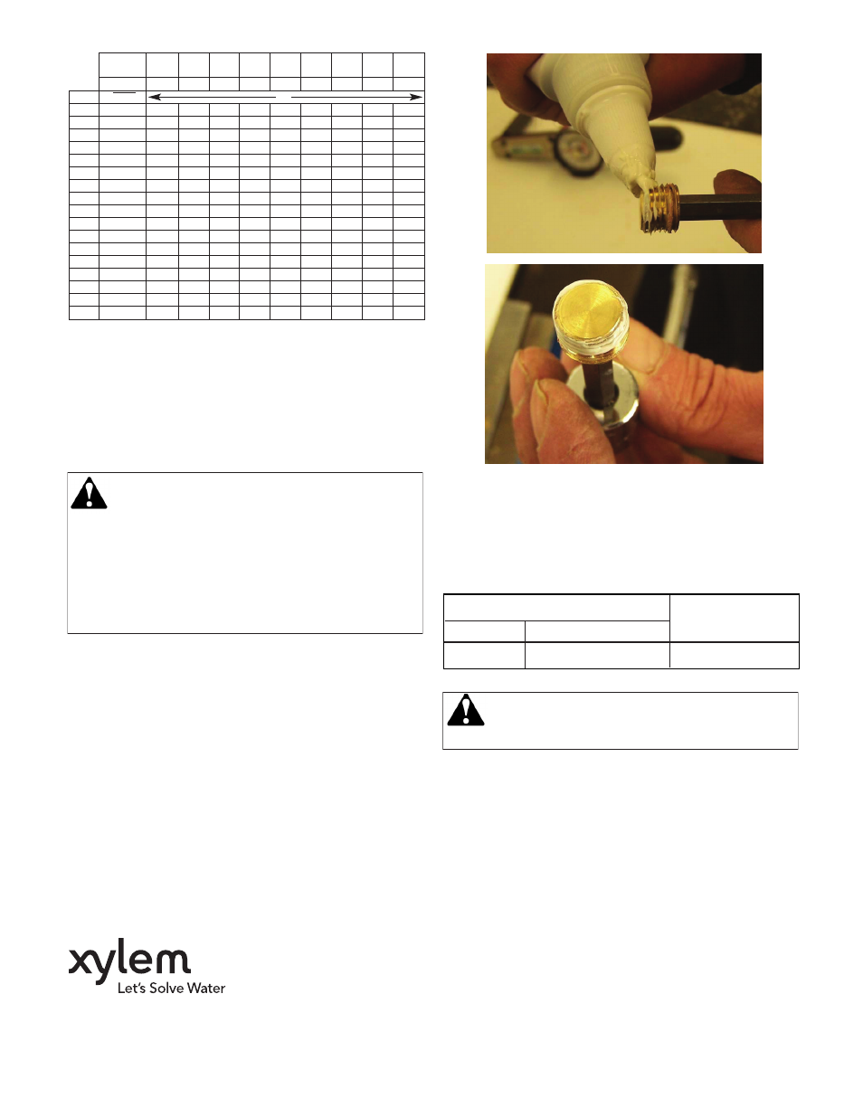
3. Starting with the second thread of the NPT male valve
component, apply a 360° bead of Loctite 567 thread seal-
ant/lubricant as shown below. Follow Loctite handling pre-
cautions as noted on the product labeling.
4. If Loctite 567 is unavailable, we recommend Rector Seal
No. 5 pipe thread sealant for all non-glycol based applica-
tions, or any PTFE thread sealing tape. Be sure to follow
the manufacturer specific handling precautions and appli-
cation instructions as noted on the product labeling.
5. Thread component into valve until it is finger tight.
6. Apply torque to the following specifications:
NOTICE: The use of thread sealants/lubricants on
threads also provides lubricity. Over application of
torque may cause damage to the valve port or component.
7. Properly assembled valve components will immediately
seal to moderate pressure (100 PSI or less). For maximum
pressure resistance, allow the Loctite 567 or Rector Seal
No. 5 thread sealant to cure for 24 hours. PTFE tape
typically does not require curing to achieve maximum
pressure resistance.
Loctite and Loctite 567 are registered trademarks of Henkel AG
& Co. Rector Seal No. 5 is a registered trademark of RectorSeal
Corporation.
Xylem Inc.
8200 N. Austin Avenue
Morton Grove, Illinois 60053
Phone: (847) 966-3700
Fax: (847) 965-8379
www.xyleminc.com/brands/bellgossett
Bell & Gossett is a trademark of Xylem Inc. or one of its subsidiaries.
© 2013 Xylem Inc. G95873N July 2013
Component
Torque
Size
Type
1/4” NPT
P/T Readout Port, Drain Plug
9.0 ft.-lbs + 3.0 ft.-lbs. / -0