Ii. remote test, Diagram 7), Remote test – C2G 13138 TC-NT1 Network Cable Tester User Manual
Page 6: Diagram 8), Patch panel wall plate
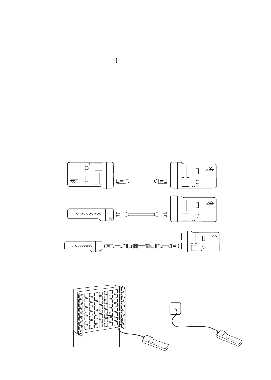
II. Remote Test
1. Plug one end of the tested cable to the transmitting RJ45 jack on the
master unit marked with a ' ' and plug the other end into the remote
terminator. If the tested cable is installed in a patch panel or wall
plate, you may use the included patch cable to solve the connector
gender problem. Please refer to Diagram7 & 8.
2. Now, set the Auto/Manual switch to Auto mode for one-person
testing.
3. Read the test results from the LED display on remote terminator.
Note: The LED display on the remote unit will scan in sequence
corresponding to the transmitting end of the master unit.
Remote Test
5
(Diagram 7)
T
R
E
N
D
n
et
T
E
S
T
P
IN
-O
U
T
I
N
D
IC
A
T
O
R
A
U
T
O
M
A
N
U
A
L
O
N
O
F
F
1
2
3
4
5
6
7
8
G
T
C
-N
T
1
N
e
tw
o
rk
C
a
b
le
T
e
st
e
r
T
R
E
N
D
n
et
T
E
S
T
P
IN
-O
U
T
I
N
D
IC
A
T
O
R
A
U
T
O
M
A
N
U
A
L
O
N
O
F
F
1
2
3
4
5
6
7
8
G
T
C
-N
T
1
N
e
tw
o
rk
C
a
b
le
T
e
st
e
r
T
R
E
N
D
n
et
R
e
m
o
te
T
e
rm
in
a
to
r
1
2
3
4
5
6
7
8
G
N
D
N
O
T
F
O
R
L
IV
E
C
IR
C
U
IT
S
T
R
E
N
D
n
et
T
E
S
T
P
IN
-O
U
T
I
N
D
IC
A
T
O
R
A
U
T
O
M
A
N
U
A
L
O
N
O
F
F
1
2
3
4
5
6
7
8
G
T
C
-N
T
1
N
e
tw
o
rk
C
a
b
le
T
e
st
e
r
T
R
E
N
D
n
et
R
e
m
o
te
T
e
rm
in
a
to
r
1
2
3
4
5
6
7
8
G
N
D
N
O
T
F
O
R
L
IV
E
C
IR
C
U
IT
S
T
R
E
N
D
n
et
T
E
S
T
P
IN
-O
U
T
I
N
D
IC
A
T
O
R
A
U
T
O
M
A
N
U
A
L
O
N
O
F
F
1
2
3
4
5
6
7
8
G
T
C
-N
T
1
N
e
tw
o
rk
C
a
b
le
T
e
st
e
r
Remote Test
Patch Panel
Wall Plate
(Diagram 8)