Iii. installation, Asus xg-dls motherboard layout, 12 asus xg-dls user’s manual – Asus XG-DLS User Manual
Page 12: Motherboard layout iii. inst alla tion, Intel, 440gx agpset, Asus asic, X g - d l s, Fast- ethernet chipset, Adaptec
12
ASUS XG-DLS User’s Manual
III. INSTALLATION
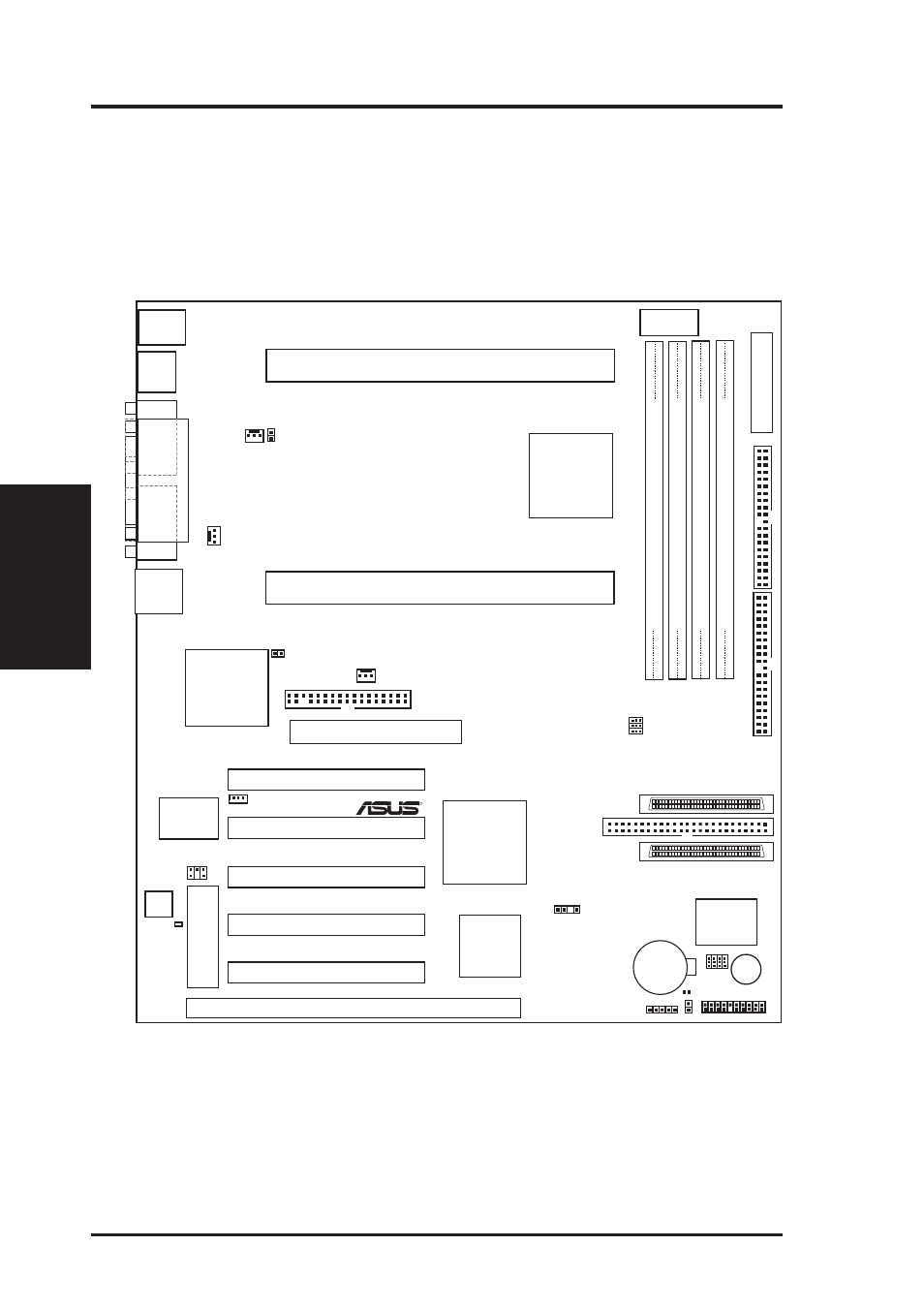
ASUS XG-DLS Motherboard Layout
Motherboard Layout
III. INST
ALLA
TION
TOP:
USB 1
BOTTOM:
USB 2
R
ISA Slot 1 (ISA1)
TOP:
Mouse
BOTTOM:
Keyboard
CR2032 3V
Lithium Cell
(BIOSPower)
Flash EEPROM
(Programable BIOS)
COM1
COM2
P
ARALLEL
PORT
PS/2
USB
Intel
®
440GX
AGPset
A
TXPWR
PCI1 (PCI Slot 1)
PCI2 (PCI Slot 2)
PCI3 (PCI Slot 3)
Intel
®
PIIX4E
PCIset
ASUS
ASIC
Multi-I/O,
Keyboard
Controller
Adaptec
®
AIC-7896
Dual Chan.
Chipset
DIMM Socket 1 (64/72 bit, 168 pin module)
DIMM Socket 2 (64/72 bit, 168 pin module)
DIMM Socket 3 (64/72 bit, 168 pin module)
0 1
2 3
4 5
ROW
DIMM Socket 4 (64/72 bit, 168 pin module)
6 7
BUS FREQ
FS1
FS2
FS0
CPU_FAN
FLOPPY
SECONDAR
Y
IDE
PRIMAR
Y
IDE
CLRTC
PCI4 (PCI Slot 4)
PCI5 (PCI Slot 5)
AGP (Accelerated Graphics Port)
PWR3V
Ultra2 (68-Pin)SCSI
Connector (Channel A)
Ultra-Fast (50-Pin)
SCSI Connector
(Channel B)
IR
PANEL Connectors
SB-LINK
35
34
68
1
35
34
68
1
1
Ultra2 (68-Pin)SCSI
Connector (Channel B)
Buzzer
PWR_FAN
CHA_FAN
Freq Mult
BF1
BF0
BF2
BF3
CHASSIS
(Intrusion)
Slot 2 Connector (for Intel
®
Xeon™ Processor)
Intel
®
Fast-
Ethernet
Chipset
WOL_CON
HDLED
CPU1TEMP
CPU0TEMP
Hardware
Monitor
Motherboard
Thermal Sensor
X G - D L S
Slot 2 Connector (for Intel
®
Xeon™ Processor)
RJ-45