Asus V4-M3A3200 User Manual
Page 72
4-14
Chapter 4: Motherboard info
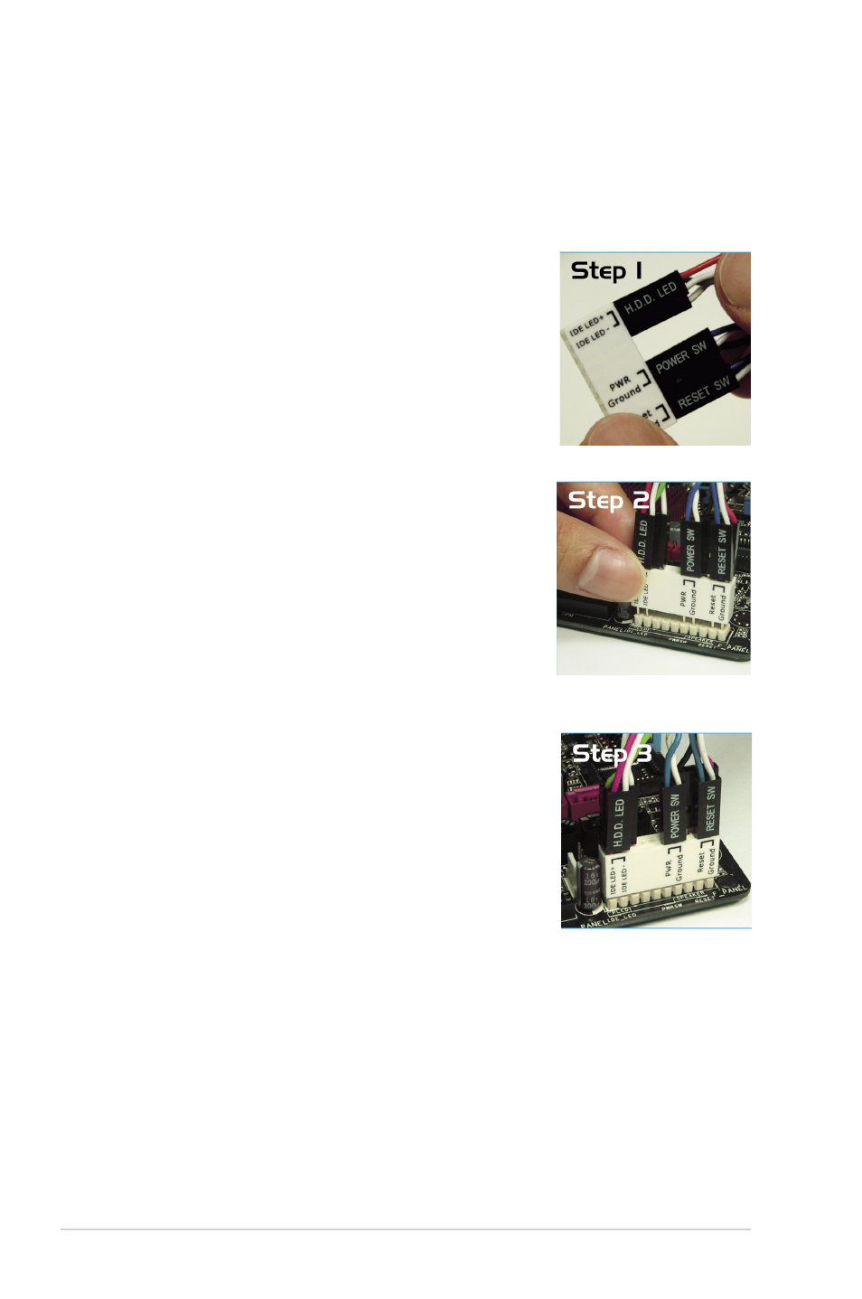
Q-Connector (system panel)
You can use ASUS Q-Connector to connect / disconnect chassis front panel
cables by only a few steps. Directions below shows how to install ASUS
Q-Connector.
Step2.
Properly install the ASUS Q-Connector to the
System panel connctor.
Step1.
Connect correct front panel to ASUS
Q-Connector first. You can refer to the
marking on Q-Connector itself to know the
detail pin definition.
Step3.
Front panel functions are enabled.
See also other documents in the category Asus Computers:
- CG8565 (410 pages)
- CG8565 (246 pages)
- CS5111 (26 pages)
- CS5120 (1 page)
- ET1611PUK (38 pages)
- S2-P8H61E (80 pages)
- P2-PH1 (80 pages)
- P1-P5945G (80 pages)
- P2-P5945GCX (90 pages)
- CG8270 (218 pages)
- CG8270 (536 pages)
- CG8270 (72 pages)
- CG8270 (76 pages)
- CG8270 (534 pages)
- CG8270 (362 pages)
- P3-PH4 (80 pages)
- P3-P5G31 (100 pages)
- P2-M2A690G (80 pages)
- P2-M2A690G (8 pages)
- P4-P5N9300 (1 page)
- P4-P5N9300 (82 pages)
- P1-P5945GC (92 pages)
- P2-P5945GC (92 pages)
- P3-P5G33 (98 pages)
- T3-P5945GC (80 pages)
- T3-P5945GCX (80 pages)
- P2-M2A690G (94 pages)
- T3-PH1 (80 pages)
- T3-PH1 (82 pages)
- T5-P5G41E (82 pages)
- T5-P5G41E (76 pages)
- S1-AT5NM10E (68 pages)
- P6-P7H55E (67 pages)
- ES5000 (174 pages)
- T4-P5G43 (104 pages)
- T-P5G31 (92 pages)
- BT6130 (60 pages)
- BT6130 (54 pages)
- BT6130 (2 pages)
- CG8265 (210 pages)
- CG8265 (350 pages)
- CM1740 (330 pages)
- CM1740 (70 pages)
- CM1740 (198 pages)
- P6-M4A3000E (59 pages)