4 internal components, 7 asus vintage v2-ph2 – Asus V2-PH2 User Manual
Page 17
1-7
ASUS Vintage V2-PH2
1.4
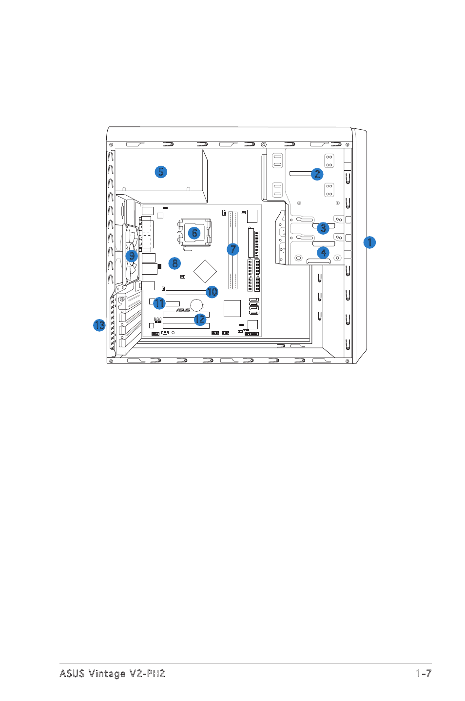
Internal components
The illustration below is the internal view of the system when you remove
the top cover and the power supply unit. The installed components are
labeled for your reference. Proceed to Chapter 2 for instructions on
installing additional system components.
1. Front panel cover
2. 5.25-inch optical drive bays
3. Hard disk drive bay
4. Floppy disk drive bay
5. Power supply unit
6. CPU socket
7. DIMM sockets
8. ASUS motherboard
9. Chassis fan
10. PCI Express x16 slot
11. PCI Express x1 slot
12. PCI slots
13. Metal bracket lock
CR2032 3V
Lithium Cell
CMOS Power
CD
Su
pe
r
I/O
4M
BIOS
LPC
ATX12V
FLOPP
Y
AAFP
DDR2
DIMM1
(64
bit,240-pin
module)
SB_PWR
USB78
USB56
PCI1
ATI
RC410
ULI
M1575
CHA_FAN2
CPU_FAN
PRI_IDE
EA
TXPW
R
SPDIF_OUT
RTL8111B
PS/2KBMS
T: Mouse
B: Keyboard
Below:Mic In
Center:Line Out
Top:Line In
USB12
LAN_USB34
PCIEX1_1
PCIEX16
COM1
PARALLEL
POR
T
VGA1
®
SATA1
SEC_IDE
DDR2
DIMM2
(64
bit,240-pin
module)
PCI2
KBPWR
AUX
TV_C
USBPW3
4
USBPW1
2
AD1986A
LGA775
CHASSIS
SATA2
SATA3
SATA4
CLRTC
USBPW56
USBPW78
PANEL
CHA_FAN1
6
1
2
3
4
13
11
9
7
8
5
12
10