Left side – Asus W3Z User Manual
Page 16
16
2
Knowing the Parts
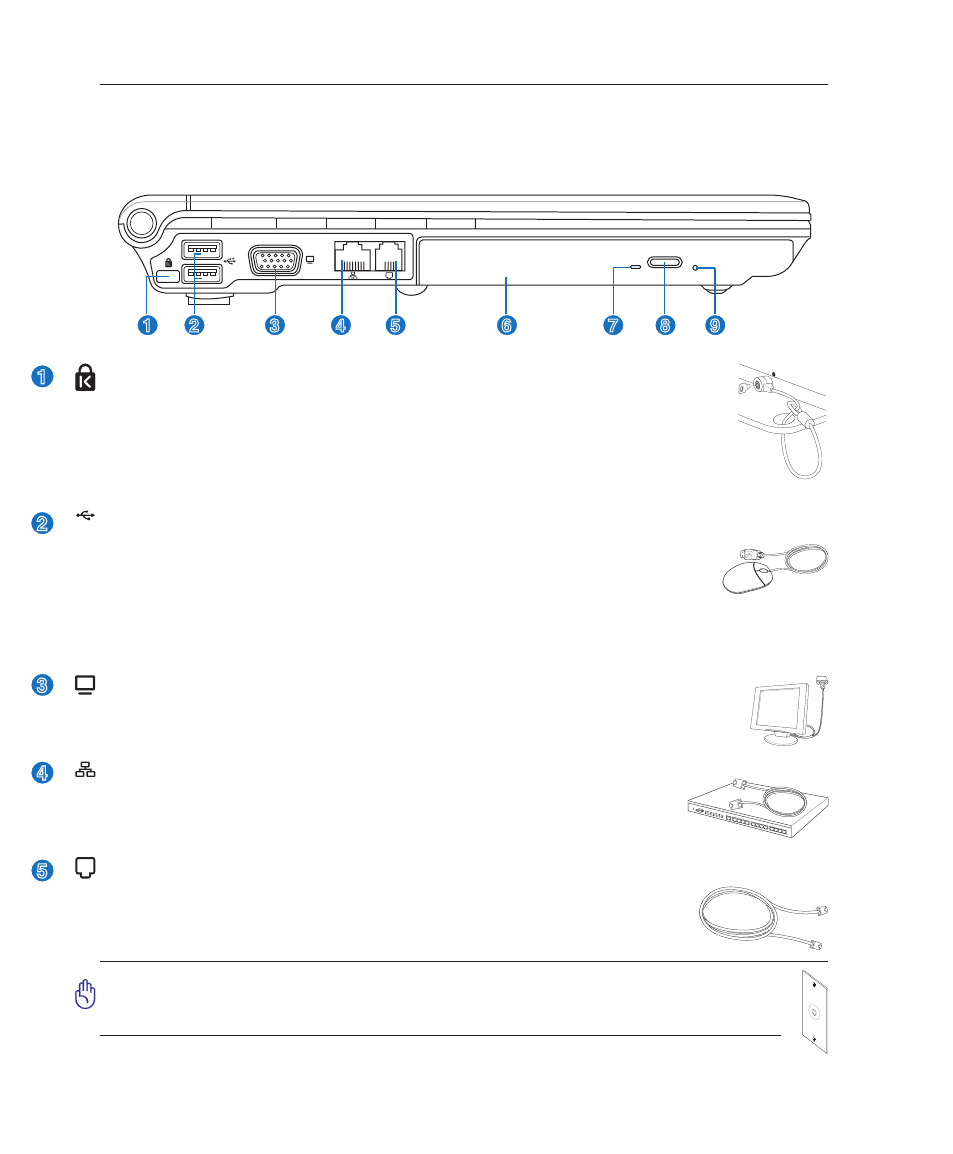
Left Side
Refer to the diagram below to identify the components on this side of the Notebook PC.
1
2
4
3
5
7
6
8
9
2
3
4
5
1
2.0
USB Port (2.0/1.1)
The Universal Serial Bus is compatible with USB 2.0 or USB 1.1 devices such as key-
boards, pointing devices, cameras, hard disk drives, printers, and scanners connected in
a series up to 12Mbits/sec (USB 1.1) and 480Mbits/sec (USB 2.0). USB allows many
devices to run simultaneously on a single computer, with peripherals such as USB key-
boards and some newer monitors acting as additional plug-in sites or hubs. USB supports hot-swapping
of devices so that most peripherals can be connected or disconnected without restarting the computer.
Display (Monitor) Output
The 15-pin D-sub monitor port supports a standard VGA-compatible device such as a
monitor or projector to allow viewing on a larger external display.
Kensington
®
Lock Port
The Kensington
®
lock port allows the Notebook PC to be secured using Kensington
®
compat-
ible Notebook PC security products. These security products usually include a metal cable
and lock that prevent the Notebook PC to be removed from a fixed object. Some security
products may also include a motion detector to sound an alarm when moved.
LAN Port
The RJ-45 LAN port with eight pins is larger than the RJ-11 modem port and
supports a standard Ethernet cable for connection to a local network. The built-in
connector allows convenient use without additional adapters.
Modem Port
The RJ-11 modem port with two pins is smaller than the RJ-45 LAN port and supports
a standard telephone cable. The internal modem supports up to 56K V.90 transfers.
The built-in connector allows convenient use without additional adapters.
IMPORTANT! The built-in modem does not support the voltage used in digital
phone systems. Do not connect the modem port to a digital phone system or else
damage will occur to the Notebook PC.